8
EN
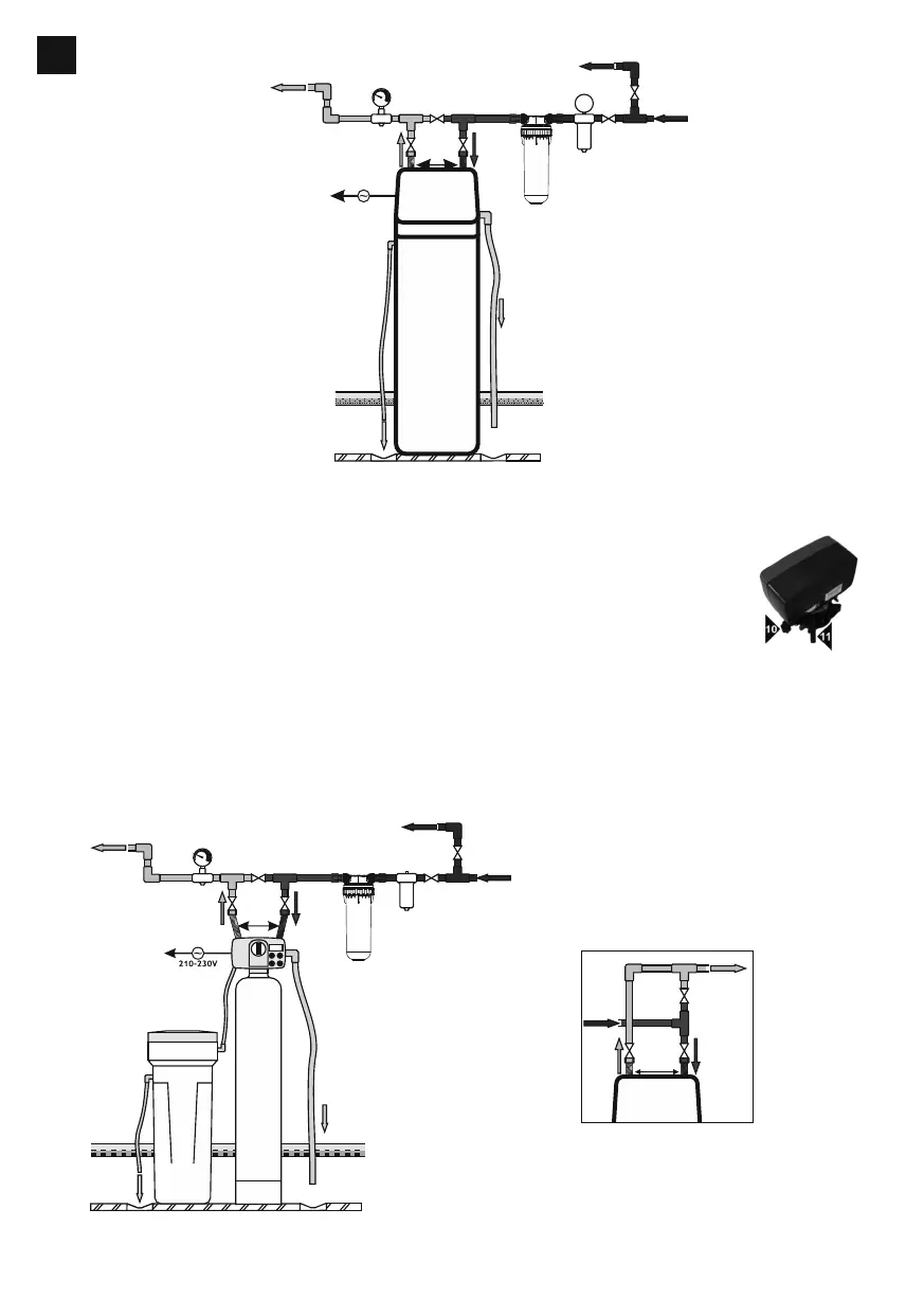
Connection diagram
of the soener
8bar
reductor
Pre-filter
alternative output to the garden
input
outflow
to the sewage system
(drain grid)
overflow of the brine tank
washings outflow
to the sewage system
air gap min 6min
drain grid
output
inputoutput
by-pass
flexible
connections
manometr
210-230V
softener
The two-element device assembly
1. Secure (seal with an adhesive tape) the pipe against the bed during the backfill
2. Pour the bedding material
3. Pour the bed provided in the set
4. Apply silicone to heads (o-rings to the vessel and guiding of the distribution pipe)
5. Install the upper basket
6. Screw the head to the vessel
7. Mount the By-passfastenerby means of fasteners (Fig.1)
8. Included connections 1" (2.2) connect to the installation (aer the water meter and/or hydrophore)
9. Connect the vessel to connections
10. Connect the exit hose
11. Hose for the brine (one side in the head to the injector bend, the second one to the float in the brine tank)
12. Connect the overflow hose.
In the case of mounting the overflow to the sewage system, a washing machine trap must be applied.
Connection diagram
of the two-element soener
by-pass with water
conncection from the le side
input
output
inputoutput
by-pass
flexible
connections
air gap min 6min
drain grid
reductor
Pre-filter
alternative output to the garden
input
brine hose
outflow
to the sewage system
(drain grid)
output
input
output
by-pass
flexible
connections
manometr
6bar
outflow
to the sewage system
(drain grid)