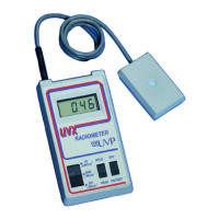
UVX Radiometer 10
• Small Phillips head screw driver
• Small straight screw driver for trimpot adjustment
Procedure
Calibration
• Remove the battery. Remove the two screws from the bottom of the case and carefully lift off the
bottom. As you do this, feed the battery clip through the aperture in the side of the battery holder.
Place the bottom of the case aside and lift the PC board out of the case top. Set the PC board on
the test bench.
• Be sure the OFF-ON/TEST switch is in the OFF position.
• Connect the DC power source to the plus and minus terminals of the battery clip. Note: The plus
side of the battery snap is the larger of the two. Set the voltage of the power supply at 9V DC.
• Connect the DC voltmeter ground connection to pin 32 of the A/D converter chip. Connect the
plus side of the DC voltmeter to pin 36 of the A/D converter chip as shown on the bottom edge of
Figure 3.
• Turn the 9V DC power on and depress the ON/TEST switch. This will apply power to the circuit.
Measure the voltage between pin 36 and pin 32.
• If the voltage is not 1.000 volts DC, adjust RV3 until this indication is obtained.
• Disconnect the voltmeter from the circuit.
• Reduce the power supply voltage to 7.00V DC.
• While viewing the display, adjust trimpot RV2 until the colon between the middle two digits just
begins to come on. Achieving this sets the low battery voltage indication circuit.
• Check for proper low battery voltage indication by reducing the supply voltage to 6.8 volts and
see that the colon is fully on. Then increase the supply voltage to 7.20V DC and see that the
colon is completely off.
• Return the supply voltage to 9.0 volts DC.
• Place the range selector switch in the 200 uW/cm
2
position.
• While viewing the display adjust trimpot RV1 until the display shows 00.0
• This completes the calibration procedure.
Ranging
• Connect the current source to the input connector as designated on Figure 4.
• Set the current source for an output of 0.00500 uA.
• Set the range switch to the 200 uW/cm
2
position. The display should now read 100.00 ±2.5
uW/cm2
• Change the current to 0.0500 uA.
• Set the range switch to the 2000 uW/cm
2
position. The display should now read 1000 ±25
uW/cm2.
• Change the current to 0.500 uA. Set the range switch to 20 uW/cm
2
. The display should now read
10.00 ±25 uW/cm
2.
• This completes the test of the ranges of the unit.
Turn off the unit by depressing the OFF switch, disconnect the power supply and test equipment and
reassemble the circuit board back into the case. Test equipment and reassemble the circuit board back
into the case.
Radiometer Maintenance
Care of Radiometer Case
The case of the UVX Radiometer is fabricated from a durable ABS plastic. As with all plastics, solvents
should not be used for cleaning of the case. A high quality plastic cleaner or mild soap and water should
be used to clean fingerprints, dust of dirt from the case.
Note: Do not use abrasive cleaners on the radiometer. The contacts for the sensor input and the recorder