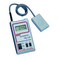
UVX Radiometer 6
• Excellent cosine response with typical curve supplied in the manual
• A filter system which significantly reduces shortwave solarization phenomenon
• Internal temperature correction retains the accuracy of the sensors at both high and
low temperatures
• Externally accessible zero adjust
• Port for a chart recorder (recorder not included)
Optional Features
• A 10 to 1 attenuator allowing readings to be made up to 200mW/cm
2
.
Specifications
Radiometer
Conversion Rate: 2.8 readings/sec
Display: 3-1/2 digit LCG
Accuracy: ±2.5%
Linearity: ±0.2%
Resolution: 1 part in 1999
Sensitivity Ranges: 0 to 199.9 µW/cm
2
0 to 1999 µW/cm
2
0 to 19.99 mW/cm
2
0 to 199.9 mW/cm
2
w/10:1 Attenuator
Temperature Coefficient: ±0.025%/°C ± 1 digit, 0 to 50°C
Zero Drift: ±0.02 uW/cm
2
/°C nominal 0 to 50°C
Power: 9V transistor battery
Battery Life (Alkaline): 120 Hrs (without recorder output option)
Sensor
Spectral Response: See Figures 7, 8, 9
Accuracy: ±5% (includes NIST standard)
Linearity: ±1.0%
Cosine Response: See Figure 10
Temperature Coefficient: ±0.04%/°C nominal, 0 to 40°C
Zero Drift: ±0.35 uW/cm
2
/°C nominal 0 to 50°C
Operating Environment
Temperature: 0 to 50°C
Humidity: 5% to 90% RH
Operating Procedures
The UVX Radiometer provides versatility and simplicity of operation. The number of front panel controls
has been held to a minimum. Range changes are made by means of a three position range switch.
Access to the zero adjust trimpot is available through the hole in the left hand side of the case. This
simplifies the operation of the instrument and also minimizes operator error.
The procedure that follows will help in understanding the operation of this instrument.
• Turn the radiometer over and open the battery cover to ascertain if the battery has been installed.
If it is has not, snap the battery clip in place on the battery and insert the battery back into the
holder. Then close the battery cover.
• Plug the UVX sensor into the mating connector at the left rear of the UVX Radiometer. This
receptacle is identified in Figure 1.
Note: The connector goes through two "snap" positions before it is fully inserted. Failure to insert the
connector all the way in will result in erroneous readings.