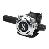
A700 Step-by-step maintenance procedures.
22. Expel o-rings
out of the
grooves (slightly)
with one set of
figures and shove
off with other.
Avoid use of
tools, they may
cause damage.
“Flow deflector”
(aspirator) need not be
removed!
If you must – it is a snap
fit. Flow deflector is
orientation specific!
23. Usage of
small profile brass
o-ring picks is
also handy – just
be careful not to
score the o-ring
lands.
26. Look inside the inlet
tube, with proper
lighting – to be sure
both lever tabs (deep
inside the inlet tube) are
present and imperfection
free.
24. Pinch and
separate the low
pressure seat.
Note: The LP seat
is a press fit.
Press in / pull
out.
27. Fully engage function
#7 into the back slots of
the adjustable orifice.
Unscrew
counterclockwise,
until threads have
disengaged, (approx. 4
rotations).
28. Expel the adjustable
orifice with care, by
pushing slowly from the
“knob” side of the inlet
tube. Your tool of choice
must clear the lever tabs
and orifice knife-edge.
29. Remove o-ring, with
soft brass pick.
30. Now thoroughly
inspect the knife-edge
surface using your
finger-nail to detect any
nicks or imperfections,
by rotating the orifice
back and forth.
Lever – need not be removed! Visually
inspect the lever to be sure an
inexperienced technician hasn‟t bent it
previously. The lever should “parallel” the
inlet tube from end-to-end.
25. Using a
magnifying glass –
inspect the poppet
“shoulders”,
marked in red -
for any signs of
wear,
due to
cam action
.
Though rare,
replace as needed.