ENGLISH
32
LED OFF ON
FLASHING led (combined with led 8)
Led 8 is OFF or ON Led 8 is BLINKING
1. start/up
On the start/up
terminal, the
contact is open
On the start /up
terminal, the
contact is closed
Start command
received from remote
control
Writing in flash at the
end of the
programming is failed
2. open/stop
On the open/stop
terminal, the
contact is open
On the open/stop
terminal, the
contact is closed
Stop command
received from remote
control or start aborted
due to stop being on
-
3. auto/down
On the down
terminal, the
contact is open
On the down
terminal, the
contact is closed
Down command
received from remote
control
-
4. photo
On the photo
terminal, the
contact is open
On the photo
terminal, the
contact is closed
Start aborted due to
inter-rupted photocell
detection
Photocell test is failed
5. edge
On the edge
terminal, the
contact is open
On the edge
terminal, the
contact is closed
Start aborted due to
pressed edge detection
Edge test is failed
6. dm/fire
On the fire
terminal, the
contact is open
On the fire
terminal, the
contact is closed
Start aborted due to
fire alarm being on
-
7. light/canc - -
Light command received
from remote control or
opening cycle* phase
indication or remote
control codes erasure
Remote control codes
erasure is failed
8. motor/test
/error
The motor is not
activated
The motor is
activated
Error indication
* Operating cycle: the 7 leds (light / delete) switch on following the logic below:
• Led off
: control unit off
• Flashing light led at 2 Hz: opening phase
• Permanent led: control unit off with shutter open (if the timer is on for automatic closing, the led
turns off briefly, every half a second)
• Flashing light led at 4 Hz
: closing phase
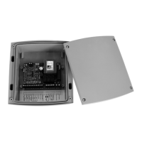
VISUALISATION AND SIGNALLING USING LED
A row of 8 red leds is fitted to the card, via which all the useful signals for installation and usage are
controlled. During the normal running of the control unit (NOT at the programming stage), the meaning of
each led can be found in the following table: