Do you have a question about the V2 City7 and is the answer not in the manual?
Details automation requirements in compliance with European safety standards.
Emphasizes installer responsibilities, required skills, and safety measures during installation.
Confirms CITY7 products meet essential requirements of EMC, Low Voltage, and Radio Directives.
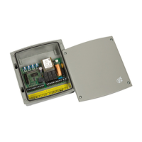
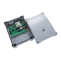
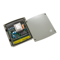
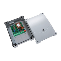
Details power supplies, input options, safety features, and programmability of the control unit.
Highlights features like trimmer adjustments, receiver compatibility, LED monitoring, and courtesy light.
Explains how to connect the power supply cables to the control unit terminals.
Details the wiring for connecting one or two asynchronous AC motors to the control unit.
Instructions for connecting blinker and courtesy light accessories to the control unit.
Explains the two settings for photocell operation: always active and not active during opening.
Details the connection of photocell transmitter and receiver power cables and output.
Describes the two modes for safety edges: always active and not active during opening.
Instructions for connecting standard and conductive rubber safety edges to the control unit.
Explains START input modes (Step/Inversion) and details device connection.
Describes the STOP input's function for immediate gate stoppage and its connection.
Explains how pedestrian start commands function for partial or full gate opening.
Details the MR1 series receiver, its compatibility, and connection to the control unit.
Maps the MR1 receiver channels to specific commands on the City7 control unit.
Provides instructions for connecting an external antenna to improve radio capacity.
Lists all terminals (L1-L11, K1-K10, J1) and their corresponding functions.
Important note on jumpering normally closed inputs when not in use.
Details the four trimmers for adjusting motor power, work time, pause, and delay.
Recommends setting operating times with the slow-down function disabled.
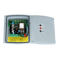
Explains the state of START, IN2, STOP, PHOTO, EDGE, mains, and overload LEDs.
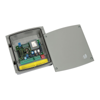
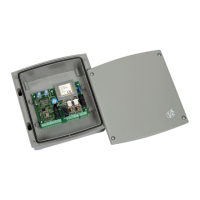
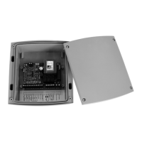
Details the casing's cable gland capacity and instructions for drilling.
Explains the functions of dip-switches 1-7 for pre-flashing, auto-closure, start, logic, slow-down, and anti-slip.
Details dip-switch settings for photocell modes (always active, not active) and testing.
Explains dip-switch settings for safety edge types (standard, conductive) and testing.
| Brand | V2 |
|---|---|
| Model | City7 |
| Category | Control Unit |
| Language | English |