ENGLISH
20
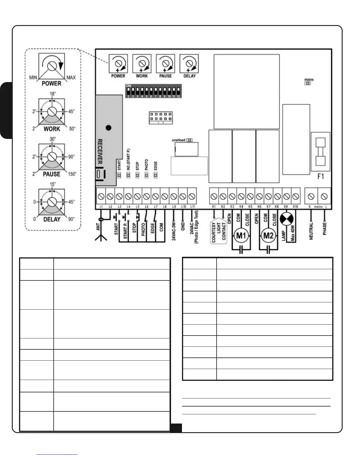
ELECTRICAL CONNECTION TABLE
L1 Antenna
L2 Antenna shield
L3
Opening command for a standard
connection device with switch
normally open.
L4
Pedestrian opening command for a
standard connection device with
switch normally open.
L5 STOP command. N.C. switch
L6 Photocell. N.C. switch
L7
Edge. Switch N.C. or resistive rubber
edge
L8 Commands common (-) line
L9 - L10
24 VAC power output for photocells
and other accessories
L10 - L11
Power supply for functional test TX
photocell
K1 - K2 Courtesy light timer activation switch
K3 Motor 1 open
K4 Motor 1 common
K5 Motor 1 close
K6 Motor 2 open
K7 Motor 2 common
K8 Motor 2 closed
K9 - K10 230V - 40W / 120V - 40W blinker
N 230V / 120V power supply - neutral
L 230V / 120V power supply - phase
J1 NOT USED
PLEASE NOTE: If not used, the normally closed
inputs (STOP, PHOTO, EDGE) must be jumpered
with the commands common line COM (-)
 Loading...