Do you have a question about the V2 EASY Series and is the answer not in the manual?
Key considerations and advice for users and installers of the control unit.
Details V2 S.p.A.'s confirmation of EASY's compliance with key EU directives and standards.
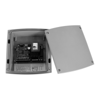
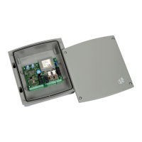
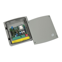
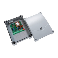
Overview of the EASY digital control unit, highlighting its features and versatility for automation.
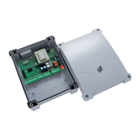
Features specific to the EASY-RI, EASY-RM, and EASY-CRI models, including radio and safety edge capabilities.
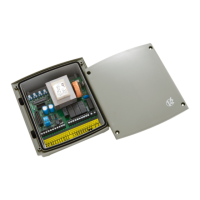
Detailed mapping of all terminals (L1-L11, E1-E5, N, mains, A1, A2) to functions and signals.
Connection for fire alarm or other alarms requiring automatic door opening.
Guidance on installing the optical safety edge with 24V DC power and transmitter adjustment.
Key technical data including power supply, motor load, working temperature, fuse, dimensions, and protection.
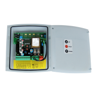
Description of control units equipped with an integrated push-button panel for UP/DOWN control.
Explanation of LED indicators and the process for programming various functions using the MENU key.
Detailed descriptions of different operating logics (Start/Stop, Step by Step, Automatic, Up/Down, Dead Man).
Procedures for testing photocell and safety edge functionality, including error indication.
Instructions on how to set the motor's working time using the MENU key and LED indicators.
Instructions on how to set the pause time for automatic re-closing using the MENU key and LED indicators.
Procedure for setting the delay time for the courtesy light to turn off after an operation.
Explanation of how remote controls operate with EASY-RM and EASY-RI/EASY-CRI models.
Step-by-step guide for saving remote controls to the control unit's memory.
How to control the courtesy light via remote control, including logic and limitations.
Procedure for deleting all stored remote control codes from the unit (EASY-RI/EASY-CRI only).
Explanation of the 8 red LEDs on the control card for status and programming indication.
Table detailing the meaning of each LED's state (OFF, ON, FLASHING) during normal operation.
Instructions for assembling cable glands into the control unit casing, including notes on drilling.
| Input Voltage | 24 VDC |
|---|---|
| Output Voltage | 24 VDC |
| Storage Temperature | -20°C to +70°C |
| Protection Class | IP20 |
| Humidity | non-condensing |