ENGLISH
10
E
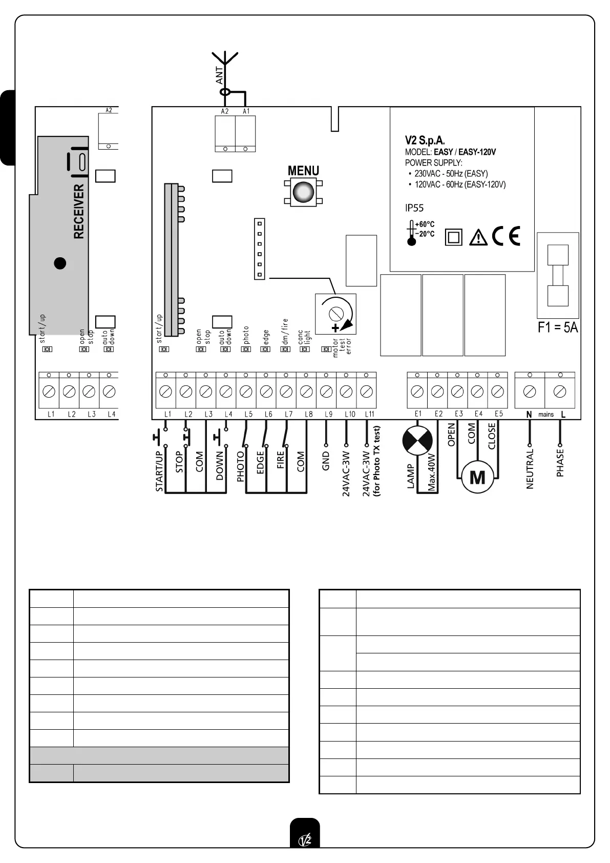
LECTRIC CONNECTIONS TABLE
L1 START/UP. N.O. contact
L2 STOP. N.C. contact
L3 COMMON (-)
L4 DOWN. N.O. contact
L5 PHOTOCELL. N.C. contact
L6 EDGE. N.C. contact
L7 FIRE. N.C. contact
L8 COMMON (-)
L9 COMMON ACCESSORIES
EASY-CRI only
L9 Adjustment of the power for OPTICAL SAFETY EDGE
L10 24VAC ACCESSORIES (24VDC for EASY-CRI models)
L11
24VAC FOR PHOTO / EDGE TEST (24VDC for EASY-CRI
models)
E1 - E2
BLINKER with built-in intermittence (230VAC / 120VAC)
COURTESY LIGHT (230VAC / 120VAC)
E3 MOTOR OPENS
E4 COMMON 230VAC / 120VAC
E5 MOTOR CLOSES
N NEUTRAL 230VAC / 120VAC
L PHASE 230VAC / 120VAC
A1 ANTENNA SHIELD
A2 ANTENNA
ATTENZIONE: Normally closed inputs STOP (L2),
PHOTOCELL (L5), EDGE (L6), FIRE (L7), if not used must be
bridged through the COMMON terminal (-)
WARNING: a wrong connection of the antenna
compromises seriously the RADIO working of the control
unit.
EASY-RM EASY-RI / EASY-CRI
EASY-CRI only