ENGLISH
21
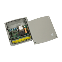
ADJUSTMENT OF THE POWER AND
OPERATIONAL TIMES
The power and operating times may be adjusted by
means of 4 trimmers located on the control unit:
POWER: motor power.
WORK: motor operating time (2 - 50 seconds).
m PLEASE NOTE: it is recommended that
operating times be set with the slow down function
disabled (DIP 5 OFF).
m WARNING: the adjustment of times has
to be made when the gate is still
PAUSE: pause time before automatic re-closure
(2 - 150 seconds).
DELAY: time delay between the two gate
leaves (0 - 90 seconds).
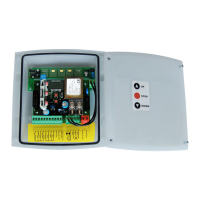
CONTROL UNIT INDICATORS (LEDS)
The highlighted boxes indicate the state of the LEDs
when the gate is resting.
LED ON OFF
START START input closed START input open
IN2 START P. input closed START P. input open
STOP STOP input closed STOP input open
PHOTO PHOTO input closed PHOTO input open
EDGE
Standard edge
EDGE input closed (edge not pressed) EDGE input open (edge pressed)
Resistive rubber edge
EDGE input closed (edge pressed)
EDGE input open (fault)
Edge NO pressed: 8K2 between EDGE input
and common (-)
mains Control unit powered-up Control unit NOT powered-up
overload Accessory power supply overload
Accessory power supply within normal
operational limits
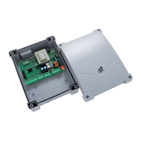
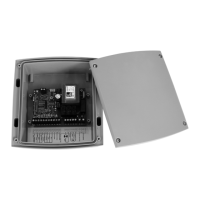
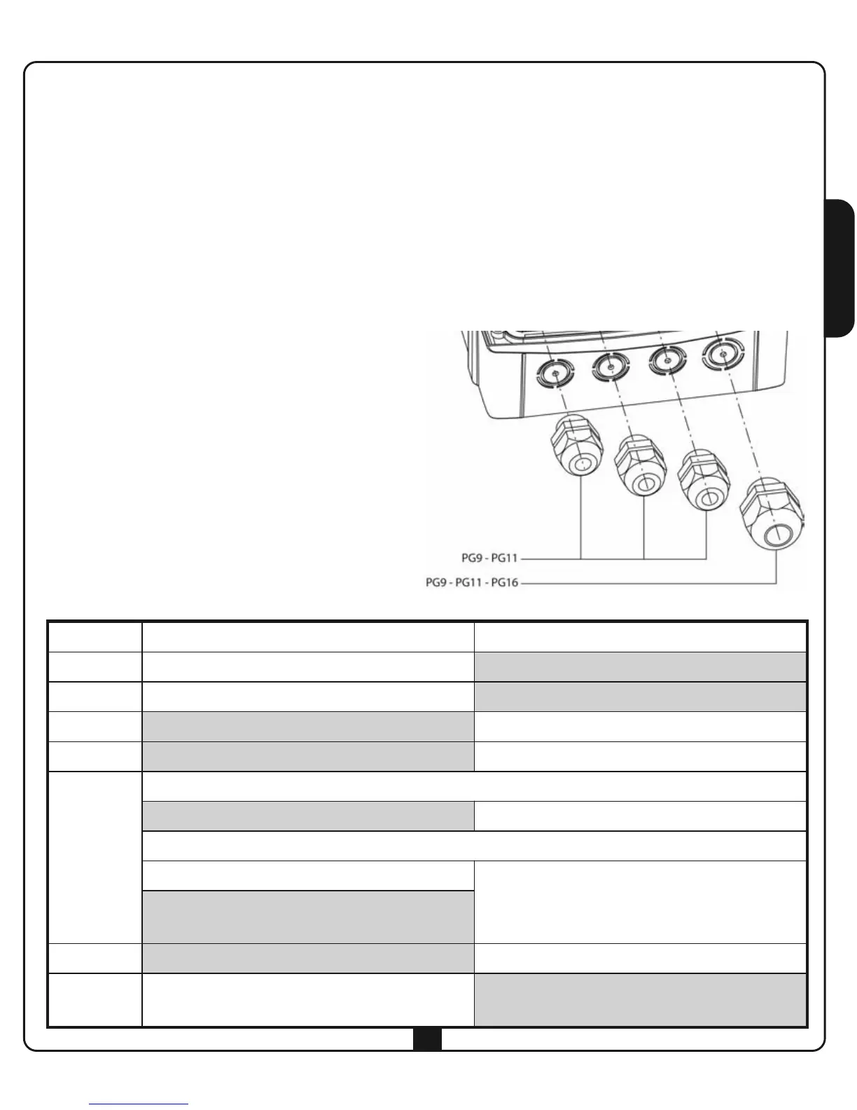
CABLE GLAND ASSEMBLY
The casing can accept 4 cable glands in the special
easy-break housings.
The type of cable gland is indicated in the figure.
m PLEASE NOTE:
• Remove the electronic circuit board before drill
the casing.
• Drill the container using a suitably sized cutter,
according to the dimensions of the cable gland.
• Fix the cable glands using the special nuts.
 Loading...