ENGLISH
- 12 -
g
g
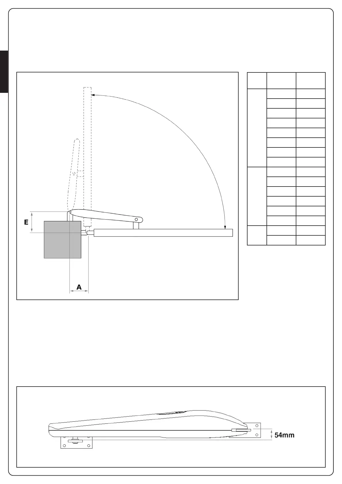
E [mm] A [mm]
90°
130 170
140 165
150 160
160 150
170 150
180 145
190 135
200 130
100°
130 155
140 150
150 145
160 140
170 140
180 135
110°
130 155
140 155
FIG.2
BRACKETS HEIGHT
Fix the brackets keeping 54 mm between the surfaces in order
tofix the gear-motor horizontally. (FIG.3).
INSTALLATION MEASURES
To carry out a proper installation of the operator parts as well as
to ensure the best automation performance, the measurement
levels shown in the following table shall be complied with.
Change the gate structure to adapt it to one of the cases in the
table, if necessary.
FIG.3
 Loading...