ENGLISH
- 14 -
ELECTRICAL CONNECTION
m CAUTION!
• A wrong connection can cause faults or danger; therefore
follow scrupulously the connections set out.
• Perform the connection operations when the electricity is off.
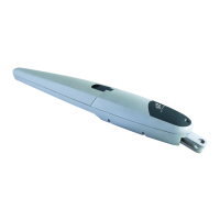
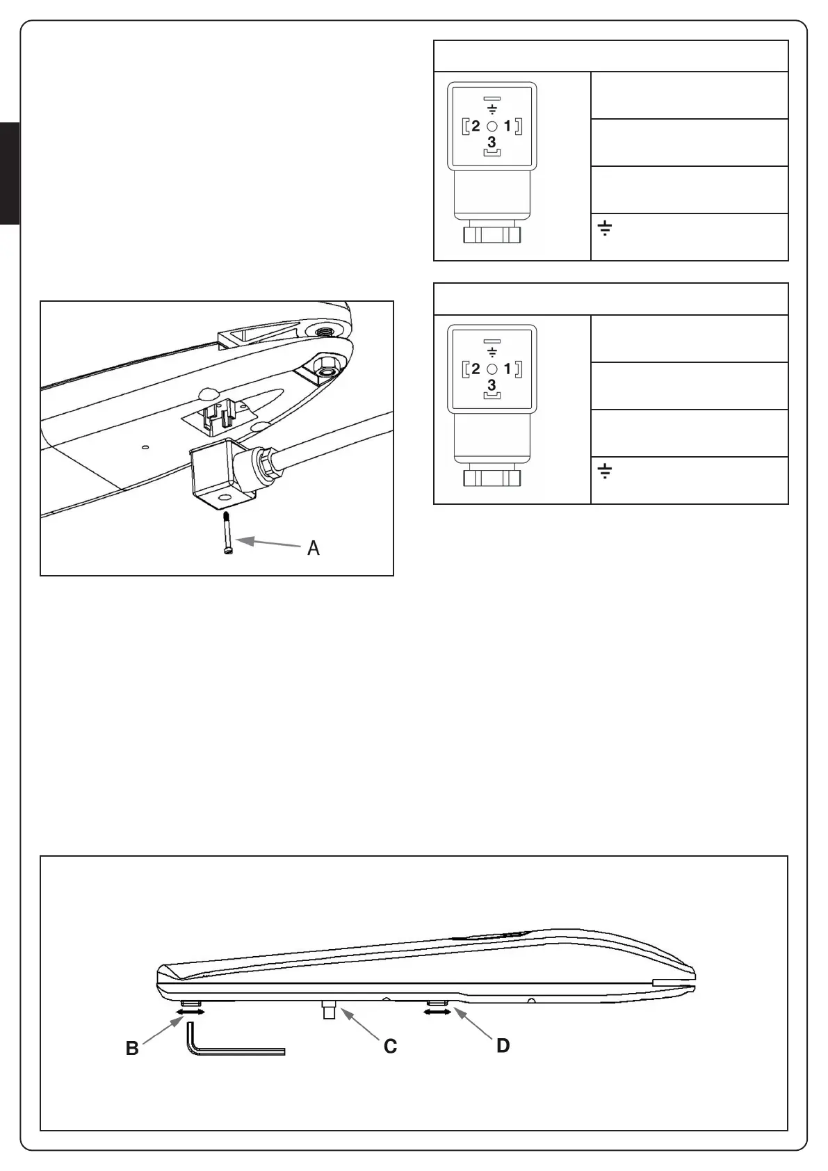
The actuator is provided with the assembled connector.
Disassemble the connector by unscrewing the screw “A”, then
connect the wires according to the diagram below.
STOP ADJUSTMENT
The mechanical-stop enables to stop the gate at a required
position, avoiding the door to hit the stop devices.
• Set the gear-motor on manual override (FIG. 6).
• Twist off the screw of the mechanical-stop (B or D).
• Move the door to the desired opening/closing position.
• Place the mechanical-stop next to the sliding pin (C).
• Turn the screw tightly.
• Set the gear-motor on automatic functioning (FIG. 7).
m WARNING: The gear-motors are normally provided
with mechanical stop in open position. In case of lack of
external mechanical stop in closing position, it is possible to
buy the optional mechanical stop.
FIG.8
FIG.9
STARK3-24V
1 - MOTOR (+)
2 - MOTOR (-)
3 - NOT USED
- GROUND
STARK3-230V
1 - PHASE 1
2 - PHASE 2
3 - COMMON
- GROUND
To check the connections, direction of rotation of the motor,
phase shift in the movement of the leaves and setting the
limit switch, refer to the instructions manual of the control
unit.
 Loading...