Vacon Plc Phone: +358-201 2121 Fax:+358-201 212 205
Service: +358-40-8371 150 E-mail: vacon@vacon.com
E-mail: application.team@vacon.com
Vacon Page 59
Pump control with autochange
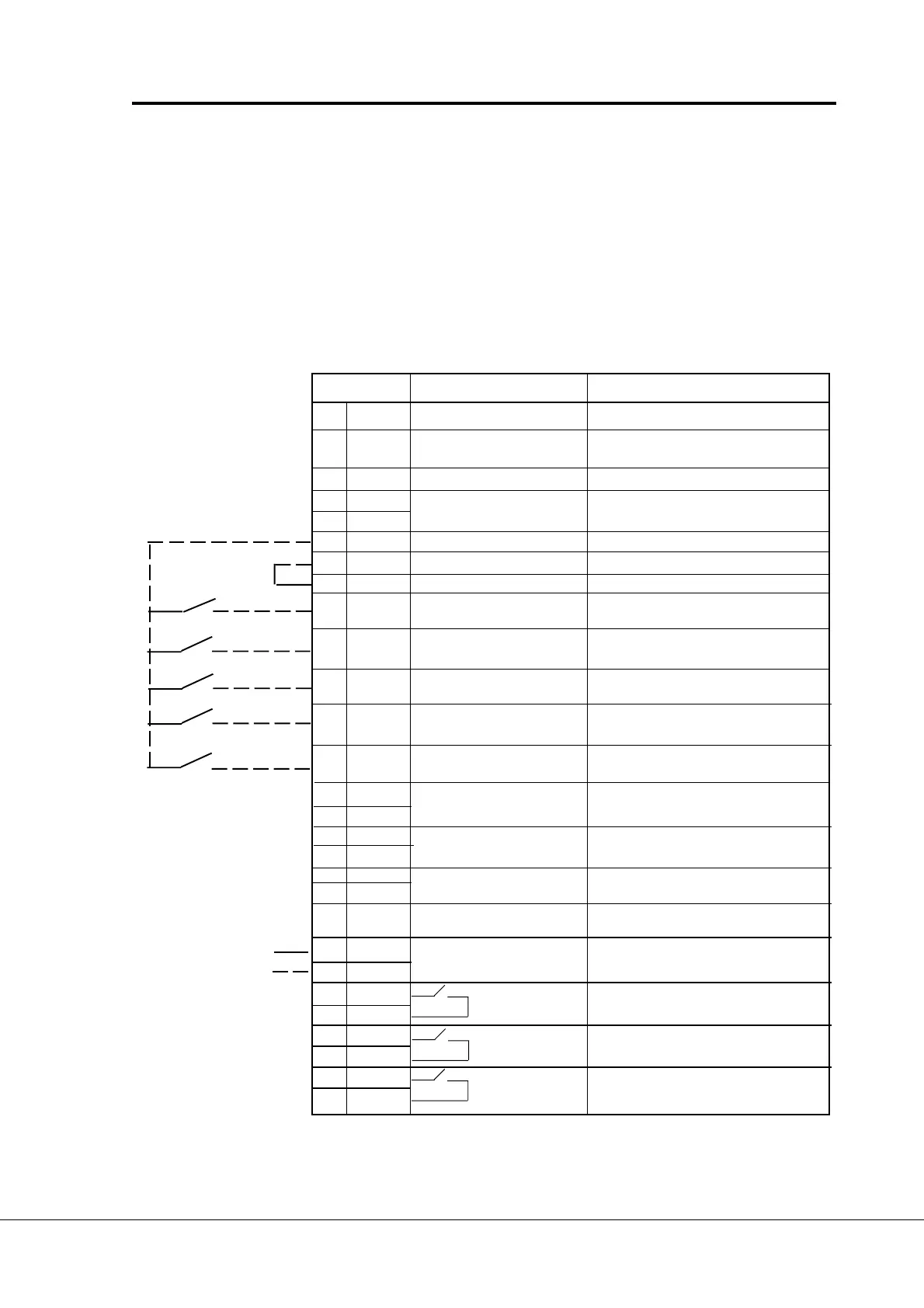
7 I/O-expander with pump and fan control application
The digital inputs and relay outputs of the I/O-expander board has fixed signals according to
figure 6-1 when the pump and fan control application is selected.
Digital inputs are used for interlock inputs and they all or part of them are active if the use of
interlocks is set active with parameter 9.31. Number of auxiliary drives (par, 9.1) defines
how many inputs are active. The controls of auxiliary drives are connected to relay outputs.
If four- or five-pump autochange is in use then the relay outputs of the basic control board
can be used additionally.
Terminal Signal Description
201 +10V
ref
Reference output Voltage for a potentiometer, etc.
202 U
in
+ Analogue input, voltage Programmable
range 0—10 V DC (Default: Not in use)
203 GND I/O ground Ground for reference and controls
204 I
in
+ Analogue input, current Programmable
205 I
in
- range 0—20 mA (Default: Not in use)
206 +24V Control voltage output Voltage for switches, etc. max. 0.1 A
207 GND I/O ground Ground for reference and controls
208 CMC Common for DIC1-DIC7 Connect to GND or + 24 V
209 DIC1 Interlock input, Contact closed = interlock is active
autochange 1
210 DIC2 Interlock input Contact closed = interlock is active
autochange 2
211 DIC3 Interlock input, Contact closed = interlock is active
autochange 3
212 DIC4 Interlock input Contact closed = interlock is active
autochange 4
213 DIC5 Interlock input, Contact closed = interlock is active
autochange 5
214 DI6A+ Pulse input A
215 DI6A- (differential input)
216 DI7B+ Pulse input B 90 degrees phase shift compared
217 DI7B- (differential input) to pulse input A
218 DI8Z+ Pulse input C one pulse per one revolution
219 DI8Z- (differential input)
220 I
out
+ Analogue output Range 0—20 mA/R
L
max. 500 Ω
Programmable
221 TI+ Termistor input
222 TI-
223 RO3 Relay output 3 Aux. drive 1 / Autochange 1 control
224 RO3
225 RO4 Relay output 4 Aux. drive 2 / Autochange 2 control
226 RO4
227 RO5 Relay output 5 Aux. drive 3 / Autochange 3 control
228 RO5
Signal from
motor termistors
Figure 7-1 I/O-expander with pump and fan control application
 Loading...