Vacon Plc Phone: +358-201 2121 Fax:+358-201 212 205
Service: +358-40-8371 150 E-mail: vacon@vacon.com
Page 4 Vacon
Pump and fan control with autochange
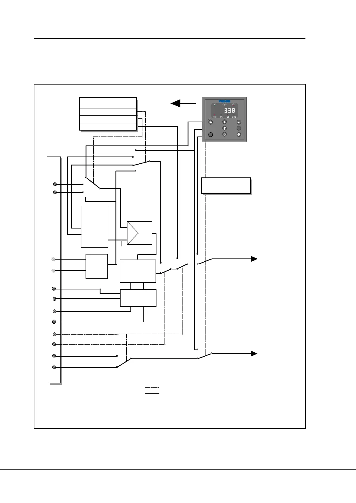
The logic of I/O-control signals and push button signals from the panel are presented in the figure
3-1.
3 Control signal logic
Figure 3-1 Control signal logic of the Pump and fan control Application.
Switch positions shown correspond to the factory settings.
U
in
+
I
in
–
DIB5
DIA2
DIB6
DIA3
DIA1
P
P
DIB4
P
I
DIA3
DIA2
pfcauto.fh3
RST
PG
RO1
RO2
Internal
frequency
reference
Internal
Start/Stop
=
control line
=
signal line
Down
PROGRAMMABLE
PUSH-BUTTON 2
Motorised
potentio-
meter
reference
Autochange 2
PARAMETERS
2
.
26 Source B ref. select.
2
.
15 Source A ref. select.
4
.
12 Jogging speed ref.
PI-controller
Reference,
Source A
Freq. ref.,
Source B
Actual
value
Up
Actual value
selection
S tart/Stop, source A
Start/S top, source B
Jogging speed s
(Programmable)
Calculation of
freq. re f. and
control logic of
auxiliary drives
Interlock 1
Interlock 2
Autochange
logic
Source A/B select.
Autochange 1
 Loading...


