8
6.2 INSTALLATION DIAGRAM
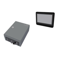
Below the configuration where two T-/TT-sense sensors are connected to the SDB-3. The Bridge Panel
PC is connected to the SDB-3 via the Ethernet cable as shown in below figure.
Figure 3 – Installation diagram SDB3 to the Bridge Panel PC with two T-/TT-Sense
6.3 INSTALLATION INSTRUCTION OF THE SDB-3 AND BRIDGE PANEL PC SYSTEM
The VAF ShaPoLi solution consists of a SDB-3 and a Bridge Panel PC. T-Sense
®
or TT-Sense
®
sensors or 3
rd
party Torque meters, NMEA inputs will be connected to the SDB-3. The SDB-3 will
perform all calculations and data processing to the Bridge Panel PC.
The Bridge Panel PC is connected to the SDB-3 via the Ethernet cable as shown in below figure.