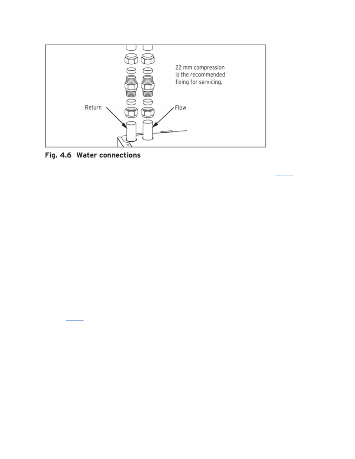
Provision is made for the water connections to be made from above the boiler, see fig 4.6 (using
the two 22mm compression couplers supplied). The position is shown on the wall template.
Flush out the domestic hot water and the heating systems before connecting to the boiler.
4.3.5 Condensate trap and siphonic drain connection
The condensate drain pipework must have a continuous-fall (45 mm per metre) and should
whenever possible terminate at a suitable drain point within the heated en-velope of the building
that will remain frost free under long periods of low external temperatures.
● During installation remove all burs from inside of cut pipe work and avoid excessive
adhesive which may trap small pockets of water close to the pipe wall which can freeze
and build into a larger ice plug.
● As with other pipe work insulate the condensate dis-charge pipe to minimise any risk of
freezing and be-ware when crossing cavities that the fall is maintained and the pipe
sleeved.
Refer to fig 4.5.
The condensate drain connection is at the underside rear of the boiler.
The condense drain is suitable for use with standard overflow pipe and couplings do not use
adhesive when connecting to the spigot (1) The condense drain pipe (2) should be plastic. The
drain pipe should have a continuous fall of a least (45mm per metre) away from the boiler.
Condensate should, if possible be discharged into the household internal drainage system.
The condensate is discharged periodically in ‘slugs’ by siphonic action.