4 Set-up
8 Installation and maintenance instructions ecoTEC plus 0020134823_07
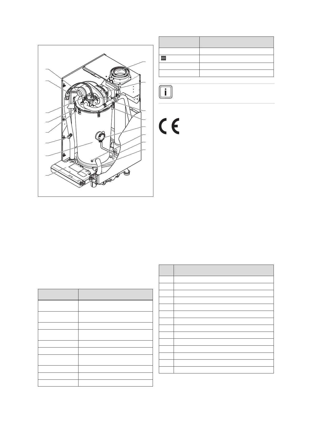
3.1.2 Functional element (1006/5‑5 and 1206/5‑5)
1 Connection for the
air/flue pipe
2 Fan
3 Gas pipe
4 Supply air connector
5 Flue pressure switch
6 Return temperature
sensor
7 Safety cut-out (flue gas)
8 Water pressure sensor
9 Electronics box
10 Integral condensation
heat exchanger
11 Manometer
12 Flow temperature
sensor
13 Safety cut-out
14 Ignition electrode
15 Automatic air vent
16 Monitoring electrode
3.2 Information on the data plate
The data plate is mounted on the underside of the product at
the factory.
Information on the
identification plate
Meaning
Serial number for identification; 7th to 16th digits =
product article number
VU… Vaillant gas-fired wall-hung boiler for
heating
ecoTEC plus Product designation
H, G20 – 20 mbar
(2.0 kPa)
Gas group and gas connection pressure
as set at the factory
Cat. (e.g. II
2H3P
) Unit category
Types (e.g. C
33
) Gas-fired boiler types
PMS (e.g. 6 bar
(0.6 MPa))
Permissible total overpressure
T
max.
(e.g. 85 °C) Max. flow temperature
230 V 50 Hz Electric connection
(e.g. 260) W Max. electrical power consumption
Information on the
identification plate
Meaning
IP (e.g. X4D) Level of protection
Heating mode
P Nominal heat output range
Q Heat input range
Note
Make absolutely sure that the product is compat-
ible with the gas group at the installation site.
3.3 CE marking
The CE marking shows that the products comply with the
basic requirements of the applicable directives as stated on
the data plate.
The declaration of conformity can be viewed at the manufac-
turer's site.
4 Set-up
For fault-free operation and a long service life for the
product, you must only install the product in installations with
system separation (plate heat exchanger).
4.1 Unpacking the product
1. Remove the product from its box.
2. Remove the protective film from all parts of the product.
4.2 Checking the scope of delivery
▶ Check that the scope of delivery is complete and intact.
4.2.1 Scope of delivery
Num-
ber
Designation
1
Unit mounting bracket
1
Heat generator
1
Condensate trap
1 Condensate discharge hose
1
Mounting template
1
Enclosed documentation
1
Enclosed unit fastening
1
Bag with small parts
1
Gas connector
1
Service valve (1 1/2 inches), red handle
1
Service valve (1 1/2 inches), blue handle
1
Bag with seals for service valves
1
Expansion relief valve, 6 bar
1
R 1 straight-through gas valve

 Loading...


