Replacing components
Installation and maintenance instructions ecoTEC 0020173113_01 65
14
> Remove the plug from the gas valve (7, ¬ fig. 14.2).
i
The plug on the fan motor has a latching lug
with which it engages in the slot. You have to
release the latching lug by pushing it in to pull
off the plug.
> Remove the plug (6, ¬ fig. 14.2) from the fan motor.
> Unscrew either the cap nut (2, ¬ fig. 14.3) from the gas
valve or the cap nut (8, ¬ fig. 14.2) between the gas
pipes.
> Secure the gas pipe against twisting by holding the pipe
against the spanner flat when undoing the cap nut.
> Unscrew the three screws (2-4, ¬ fig. 14.2) between the
mixture pipe (1, ¬ fig. 14.2) and the fan flange.
1
2
14.3 Removing the gas valve from the fan
> Remove the entire fan/gas valve unit from the boiler.
> If you want to replace the gas valve, unscrew the cap nut
(2, ¬ fig. 14.3) if the gas pipe is still secured to the gas
valve.
> Unscrew the two fixing screws (1, ¬ fig. 14.3) from the
gas valve and remove the fan from the gas valve.
> Replace the defective fan or the defective gas valve.
> Fit the gas valve and the fan in the same position as
before. Use new seals.
> Screw the fan to the gas valve.
> If you had replaced the gas valve, screw the cap nut of
the gas pipe (2, ¬ fig. 14.3) only loosely to the gas valve.
Only tighten the cap nut on the gas valve after complet-
ing the installation work.
> Refit the entire fan/gas valve unit in reverse order. You
must use a new seal for this (5, ¬ fig. 14.2).
> Pay attention to the order in which the three screws
between the fan and the mixture pipe are screwed in, as
per the numbering 3, 2 and 4 (¬ fig. 14.2).
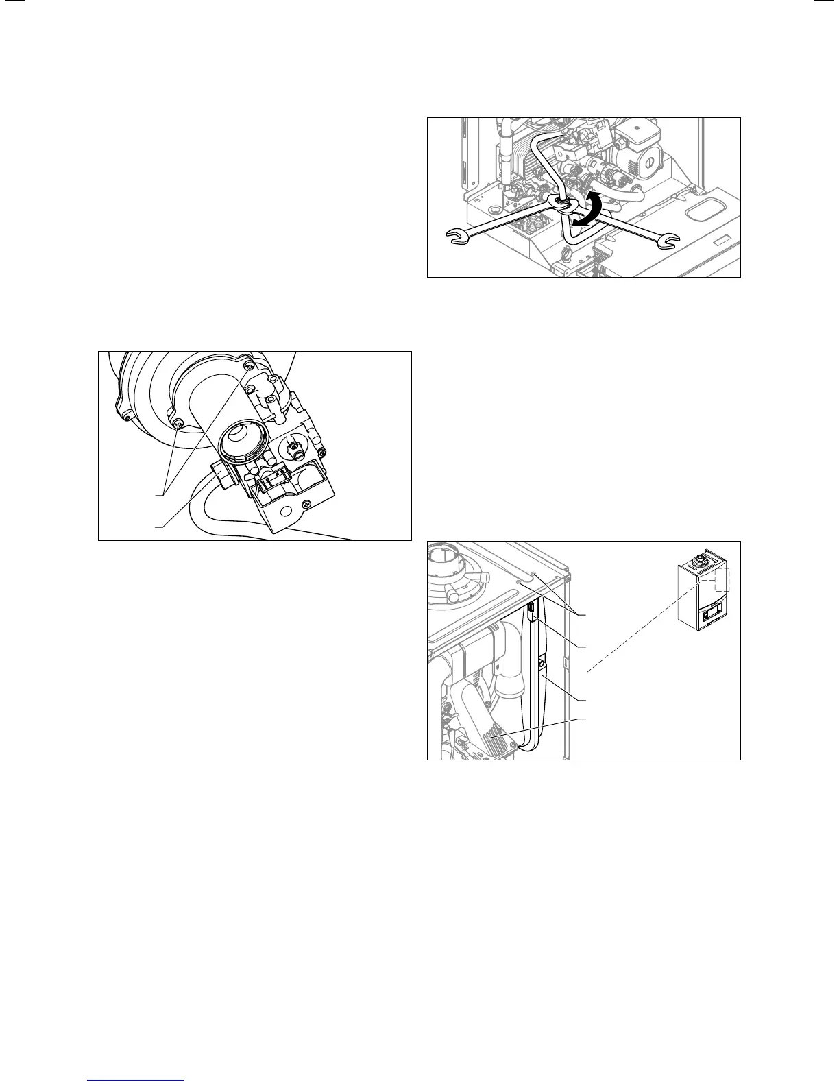
14.4 Secure the gas pipe against twisting
> Tighten the cap nut (2, ¬ fig. 14.3) on the gas valve and
the cap nut (8, ¬ fig. 14.2) between the gas pipes. Use
new seals.
> Secure the gas pipe against twisting (¬ fig. 14.4) by
holding the pipe against the spanner flat when tighten-
ing the cap nut.
> After completing the work, perform a gas-tightness
check and function check (¬ section 10.13).
> If you have fitted a new gas valve, adjust the gas setting
(¬ section 10.10).
14.4 Replacing the expansion vessel
> Drain the boiler (¬ section 12.2.2).
1
2
3
4
14.5 Replacing the expansion vessel
> Loosen the screw connection (4) at the water connec-
tion on the underside of the expansion vessel.
> Remove both screws (1) on the support plate (2).
> Remove the support plate (2).
> Pull out the expansion vessel (3) from the front.
> Insert the new expansion vessel into the boiler.
> Screw the new expansion vessel to the water connection.
Use a new seal for this.
> Attach the support plate using both screws (1).
> If necessary, adjust the pressure to the static height of
the heating installation (¬ section 12.3.7).