29Installation instructions geoTHERM VWS/VWW 0020057444_01
6.4.4 Connecting external components
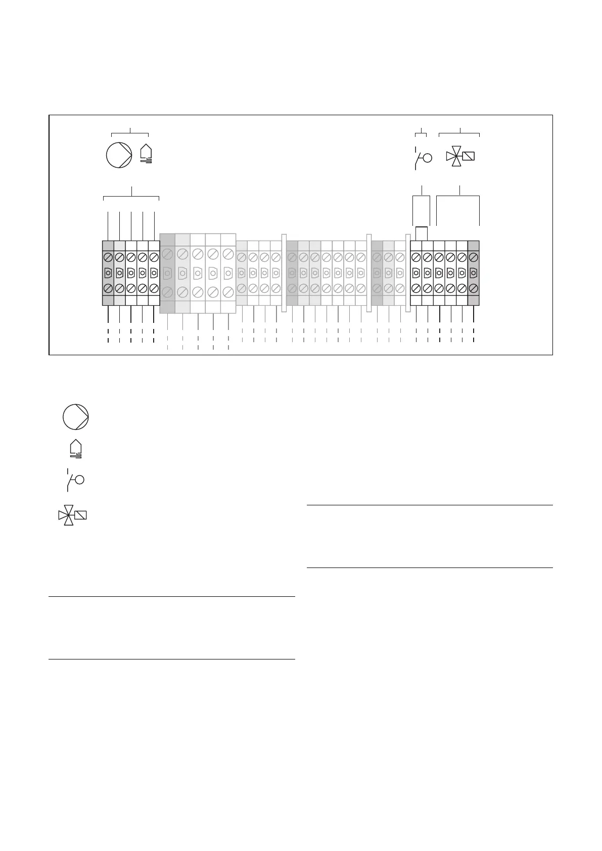
L3 L2 L1 L3 L3 L3 NL2 ZL1 AN N N N PE PE
PE L2 L1 L3 N
PES S
p
(VWS)
L3 L2 L1 N PE
(VWW)
1
32
Fig. 6.5 Connecting external components
Key to Fig. 6.5
Pump
Heat source circuit
p
Brine Switch
3-way valve with solenoid
Only if the VPA Multi-cylinder or some other multi-
cylinder is installed
• Connect the external 3-way valve for the multi-cylin-
der to the terminals (3).
h
Note!
When using an external 3-way valve, the
proper functioning of the heat pump is
only assured if the valve supplied with
the VPA Multi-cylinder is used.
VWW only:
• Connect the customer-side well pump to the
terminals (1).
The well pump is connected to the 400 V three-phase
supply via the well pump contactor.
A motor protection switch in the heat pump (see Fig. 6.1,
Item 5) protects the well pump from overload. The
switch should be set to the well pump's rated current
(0.8 – 2.7 A).
a
Caution!
Risk of damage!
The well pump will not be protected from
overload unless the motor protection
switch is properly set.
VWS only:
Should you wish to connect an external brine pressure
switch to the heat pump, use the terminals (2) for this.
6.5 Connecting the start-up current limiter
(accessory)
Some power companies demand the installation of a
start-up current limiter (Art. No. 0020025744) for the
heat pump.
• Fit the start-up current limiter PCB beneath the con-
troller PCB as described in its manual (see Fig. 6.1).
• Connect the start-up current limiter in accordance
with its manual.
Electrical installation 6

 Loading...