9Installation instructions geoTHERM VWS/VWW 0020057444_01
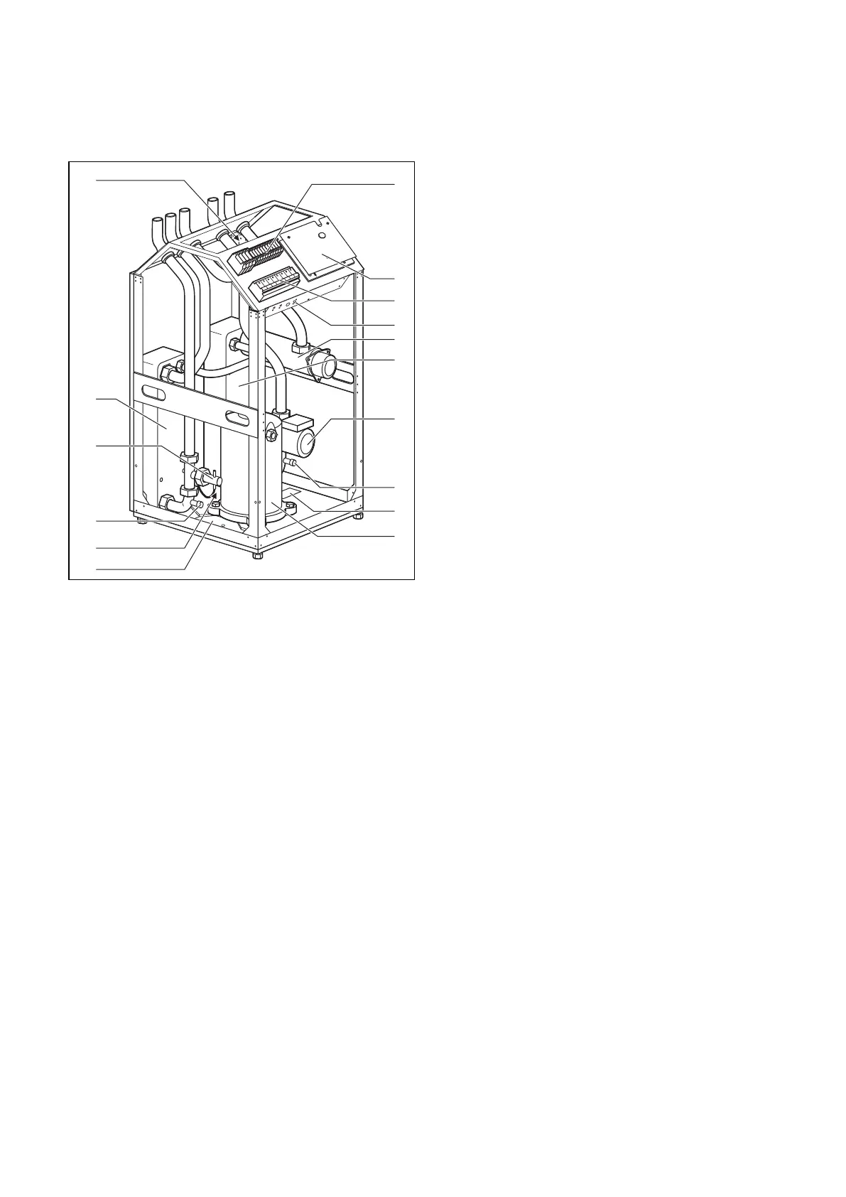
2.3.2 Component groups - VWW
15
16
14
12
11
13
1
9
3
2
5
4
6
7
8
10
Fig. 2.7 VWW - Front view, covers removed
Key to Fig. 2.7
1 Electrical connections
2 Controller PCB (under cover plate)
3 Contactors
4 Safety thermostat STL for the auxiliary heating
5 Electric auxiliary heating
6 Condenser
7 CH pump
8 Fill/drain valve for heating circuit
9 Data badge
10 Compressor
11 Condensate pan
12 Expansion Valve
13 Fill/drain valve for coolant circuit
14 Flow switch for coolant circuit
15 Evaporator
16 3-way valve
2.4 General notes on operating modes
and functions
There are five operating modes available for the heating
circuit and these can be used for time and temperature
control of the heat pump (see Chap. 8 "Control sys-
tem").
There are a further three operating modes available for
the integrated domestic hot water cylinder.
During start-up, you will tell the heat pump which of the
connection configurations listed in the appendix corre-
sponds to your installation by entering the number of
the corresponding hydraulic plan into the controller.
Thus all the operating parameters will be set to prede-
termined values, so that the heat pump can work opti-
mally. However, you can individually set and adapt the
operating modes and functions afterwards.
You will find all the information on operating modes,
auxiliary and special functions in Chapter 8, "Control
system".
The heat pump is equipped with numerous automatic
auxiliary functions to ensure trouble-free operation
(see also Chap. 8.2 "Automatic auxiliary functions"):
– Frost protection
Prevents the heating system from freezing
– Tank frost protection
Prevents the connected tanks from freezing
– Checking the external sensors
Checking the connected sensors during initial commis-
sioning using the basic hydraulic circuit that was en-
tered previously
– Protection against loss of heating water
Shuts down when there is a loss of heating water and
switches on again when there is sufficient water pres-
sure
– Pump blocking protection
Prevents seizing of pumps in the system
– Protection against loss of brine
Shuts down if the brine pressure is too low and
switches on again when the pressure is sufficient
– Floor protection circuit
Overheating protection for the floor (important for
wooden floors)
– Phase monitoring
Compressor shut-down if 400 V supply faulty
– Freeze protection function
Shuts down the compressor if the temperature of the
heat source falls below a predetermined value
Description of the device 2

 Loading...