9Operating and Installation Manual for Solar Module VR 68 0020054784_00
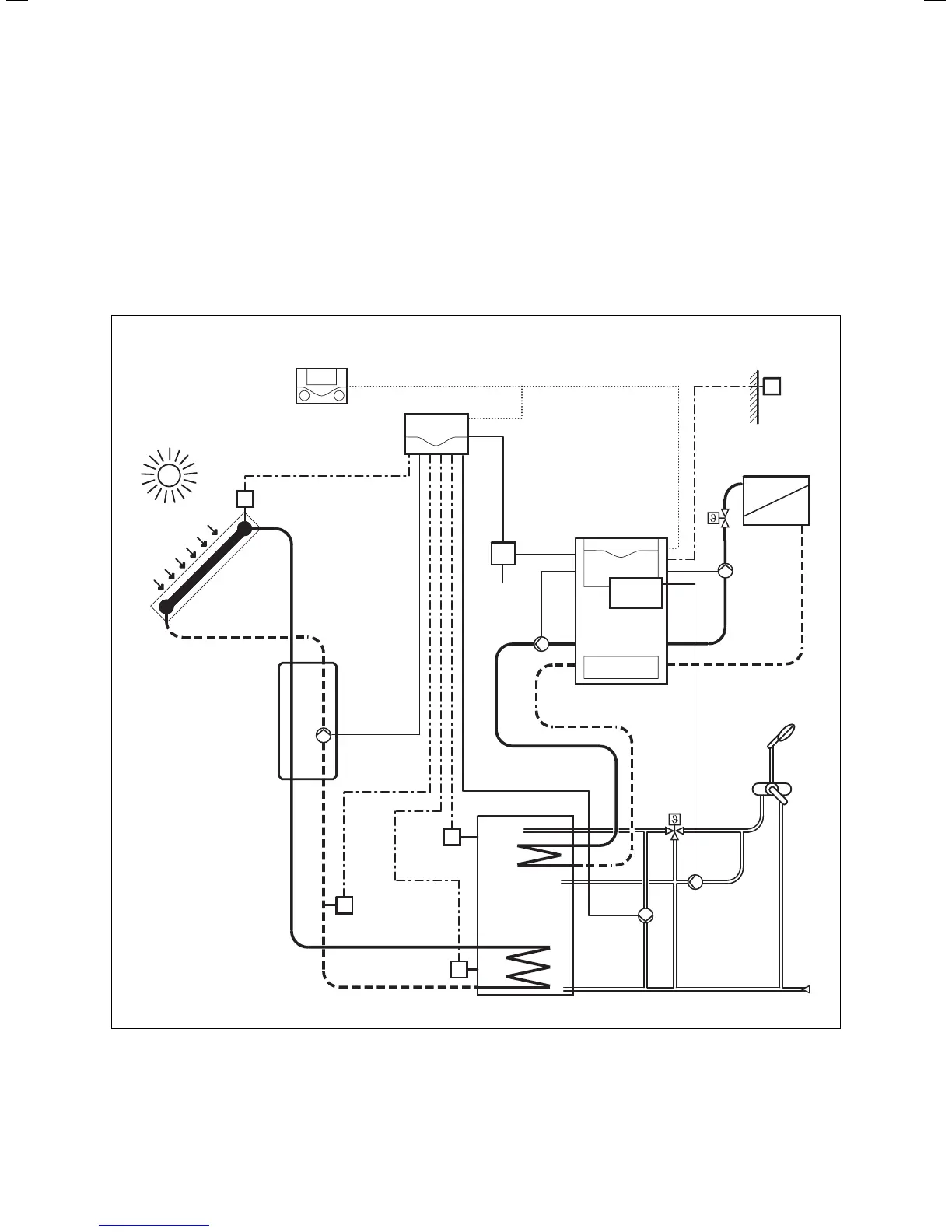
4.2 Hydraulic diagram 2
– a boiler (floor-mounted unit)
– an uncontrolled heating circuit
– a solar circuit
– a bivalent solar hot water cylinder
– charging pump for reheating bivalent solar hot water
cylinder; controlled via boiler
– circulation pump for hot water controlled by VR 40
– a legionella protection pump
VR 68
VRC 430
SP 1
(VR 10)
ZP
SP 2
(VR 10)
Ertrag
(VR 10)
KOL 1
(VR 11)
KOL 1-P
LEG-P
230 V ~
LP
HK-P
AF (VRC 693,
VRC 9535)
VR 40
Fig. 4.2 Hydraulic diagram 2
Incorporation of the VR 68 into the solar heating system 4
 Loading...