Operating and Installation Manual for Solar Module VR 68 0020054784_0018
7 Start-up
The VR 68 solar module is commissioned at the same
time as the VRC 430 or VRC 430f controller.
Proceed in accordance with the instructions in the
manual of the VRS 430 or VRC 430f controller.
7.1 Installation assistant
When commissioning for the first time you will be
supported by the installation assistant.
The most important heating system parameters can be
entered via the installation assistant.
The installation of the VR 68 solar module in the
heating system results in number of changes to the
standard configuration as described in the manual for
the VRC 430 or VRC 430f:
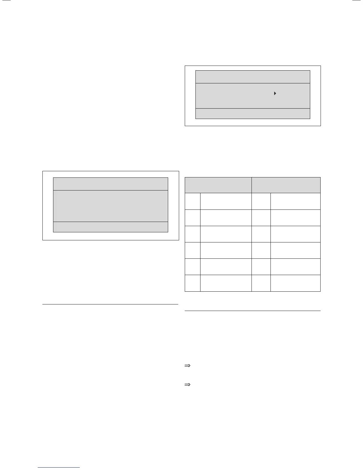
Display screen A4
Installation assistent
Solar circuit
A4
Flow rate
Litre/minute 3.5
MF-Relay 2
nd
Cylinder
Solar pump kick OFF
Solar circ. protect.
130 °C
Fig. 7.1 Installation assistant display screen A4
Display screen A4 shows the configuration of the
solar circuit.
You can adjust the rate in l/min at which the solar fluid
passes through the system under "Flow rate".
You can select the option Cylinder 2 (corresponds to
swimming pool) or the option Differential control 2
(additional) under “MF relay”.
h
Note!
If the solar heating system is designed in
accordance with hydraulic diagram 3 or 4
(swimming pool), "Cylinder 2" must be selected
at "MF relay".
Depending on the collector type used, select the
following:
- for flat collectors:
Solar pump kick = OFF
- for tube collectors:
Solar pump kick = ON.
The solar pump kick or tube collector function optimises
recording of the tube collector temperature as well as
charging or changeover where two cylinders are used.
This function should only be activated where tube
collectors are used!
To protect the solar circuit from overheating you can
use the solar circuit protection function to specify the
temperature of the collector at which the solar pump
switches off.
Display screen A5
Installation assistant
Module test
A5
Module selection VR 68
Sensors
KOL1
Actuators MA
Heating appliance OFF
> select
Fig. 7.2 Installation assistant display screen A5
You can select the components for functional testing on
display screen A5 of the installation assistant
(components are actuated briefly).
It is a pre-requisite that "VR 68" is selected as the
module selection.
Sensors Actuators
KOL1 Collector sensor MA Multifunction relay
SP1 Cylinder sensor 1 KOL1-P Solar pump
SP2 Cylinder sensor 2 LEG-P
Legionella protection
pump
Yield Yield sensor
TD1 Sensor for swimming
pool or additional
differential control
TD2 Sensor for additional
differential control
Table 7.1 Components for function test in display screen A5
a
Caution!
Improper installation/assembly may lead to
damage in the solar heating system.
Perform a function test of the components
using the installation assistant as part of the
start-up procedure.
If you wish to exit the installation assistant:
Turn the left hand adjuster of the VRC 430/
VRC 430f controller in a clockwise direction to
reach display screen A6.
Confirm the end of the installation with "Yes".
7 Start-up
 Loading...