Operating and Installation Manual for Solar Module VR 68 0020054784_006
4 Incorporation of the VR 68 into
the solar heating system
The possible applications of the VR 68 solar module are
shown in the four hydraulic diagrams.
The VR 68 solar module can be combined with the VR 61
mixer module within a solar heating system. Two heating
circuits can be controlled using the VR 61 mixer module
in conjunction with the VRC 430 or VRC 430f controller.
Hydraulic diagram 1
– a wall-mounted boiler
– an uncontrolled heating circuit
– a solar circuit
– a bivalent solar hot water cylinder
– reheating of bivalent solar hot water cylinder using
preference switching valve (VUV)
– circulation pump for hot water controlled by VR 40
– a legionella protection pump
Hydraulic diagram 2
– a boiler (floor-mounted unit)
– an uncontrolled heating circuit
– a solar circuit
– a bivalent solar hot water cylinder
– charging pump for reheating bivalent solar hot water
cylinder; controlled via boiler
– circulation pump for hot water controlled by VR 40
– a legionella protection pump
Hydraulic diagram 3
– a wall-mounted boiler
– an uncontrolled heating circuit
– a solar circuit
– a bivalent solar hot water cylinder
– reheating of bivalent solar hot water cylinder using
preference switching valve (VUV)
– circulation pump for hot water controlled by VR 40
– a legionella protection pump
– 3-way changeover valve for heating a swimming pool
using solar energy
Hydraulic diagram 4
– a boiler (floor-mounted unit)
– an uncontrolled heating circuit
– a solar circuit
– a bivalent solar hot water cylinder
– charging pump for reheating bivalent solar hot water
cylinder; controlled via boiler
– circulation pump for hot water controlled by VR 40
– a legionella protection pump
– 3-way changeover valve for heating a swimming pool
using solar energy
The following applies for all hydraulic diagrams:
H
Danger!
Risk of scalding by hot water!The solar hot
water cylinder can reach temperatures that are
considerably higher than 60 °C (not only due to
the solar heating, but also the legionella
protection function if it is active).
Make absolutely sure that your expert
technician installs a mixer valve with cold water
supply.
Have the mixer valve adjusted by your expert
technician.
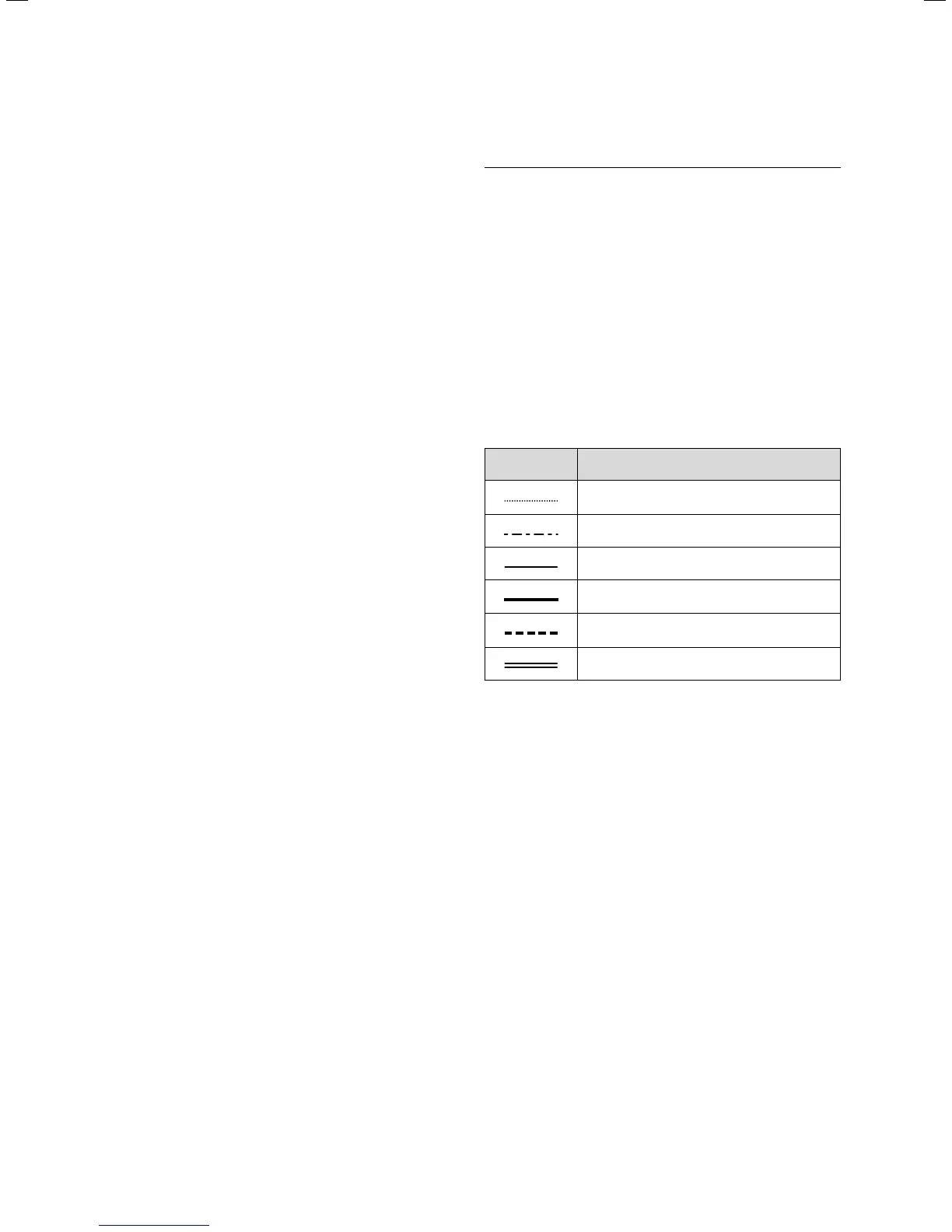
The following conventions apply in the hydraulic
diagrams:
Lines:
Representation Meaning
eBUS line twin core
Sensor line low voltage
Control line 230 V~
Heating feed, collector or swimming pool
Heating return, collector or swimming pool
Hot water feed/return, infeed
Table 4.1 Depiction of lines in the hydraulic diagrams
4 Incorporation of the VR 68 into the solar heating system