7Operating and Installation Manual for Solar Module VR 68 0020054784_00
Incorporation of the VR 68 into the solar heating system 4
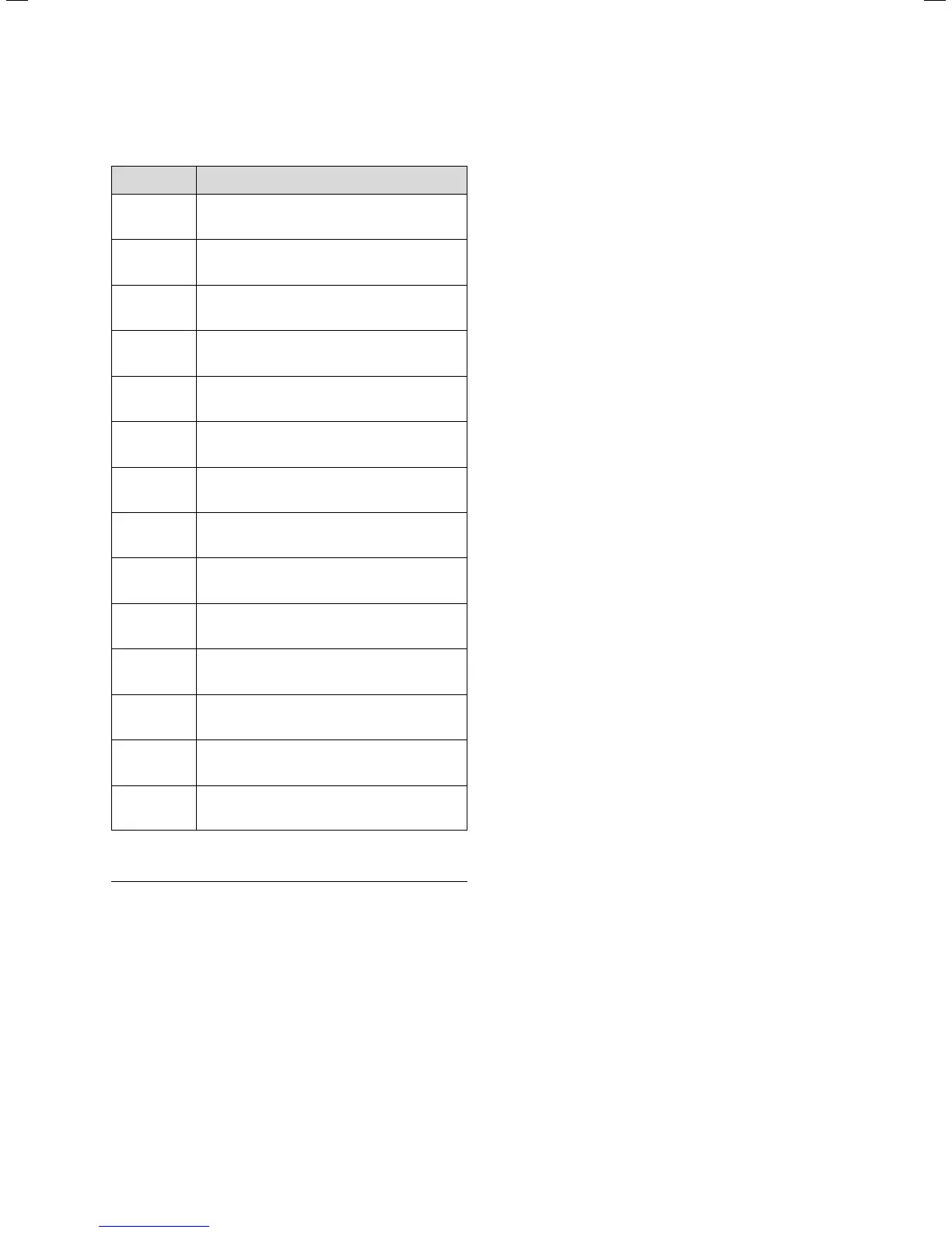
Designations:
Nomenclature Meaning
AF
External sensor (with VRC 430: VRC 693/
VRC 9535; with VRC 430f: VR20/
VR21)
Yield
(Ertrag)
Solar yield sensor (VR 10)
HK-P Pump for heating circuit
KOL 1-P Solar pump
KOL 1 Collector sensor (VR11)
LEG-P Legionella protection pump
LP Charging pump for storage tank
MA 3-way changeover valve
SP 1 Cylinder sensor 1 (VR10)
SP 2 Cylinder sensor 2 (VR10)
TD 1
Sensor for swimming pool (VR 10) in immersion
sleeve
TD 2
Sensor for differential control 2 (VR 10)
(see note below)
VR 40
Additional module (integrated in heating
equipment)
ZP Circulation pump for hot water
Table 4.2 Designations used in hydraulic diagrams
h
Note:
Sensor TD 2 is only used to realise an optional
additional differential temperature control
(TD 1 - TD 2) in conjunction with sensor TD 1
and multifunction relay output MA. Observe
that the specific configuration which is
necessary with this hydraulic variant can be
carried out with the aid of the installation
assistant (also see Section 7.1):
The "differential control" option must be
selected under "MF relay" on display screen
A4. The corresponding hydraulic diagram is not
shown here. It is then no longer possible to heat
a swimming pool using solar energy.