Operating and Installation Manual for Solar Module VR 68 0020054784_001414
5 Assembly
The VR 68 solar module is mounted on a wall near the
corresponding functional units.
The adjustment of all required parameters is carried out
using the controller VRC 430 or VRC 430f via eBUS.
All connections for the associated functional units
are established directly at the VR 68 solar module via
ProE terminals.
5.1 Scope of delivery
Before starting the installation, check the scope of
delivery for completeness and lack of damage.
Pos. Number Component
1 1 Solar module VR 68
2 3 Feed sensor VR 10
3 1 Collector sensor VR 11
4 1 Mounting accessories (screws, plugs)
Table 5.1 Scope of delivery of the VR 68 solar module
h
Note!
Depending on how the solar heating system is
configured, additional feed and cylinder sensors
may be required.
Only the standard sensor VR 10 from the
Vaillant accessories programme should be used.
The heating control using Vaillant components
is matched to the sensor characteristic curve
of the VR 10.
Temp. in °C R in kOhm Temp. in °C R in kOhm
10 5.363 55 0.806
15 4.283 60 0.671
20 3.372 65 0.562
25 2.700 70 0.473
30 2.176 75 0.399
35 1.764 80 0.339
40 1.439 85 0.288
45 1.180 90 0.247
50 0.973
Table 5.2 Standard sensor VR 10, allocation temperature
measurement value
Temp. in °C R in kOhm Temp. in °C R in kOhm
15 15.694 70 1.753
20 12.486 75 1.481
25 10.000 80 1.256
30 8.060 85 1.070
35 6.535 90 0.916
40 5.330 95 0.786
45 4.372 100 0.678
50 3.605 105 0.586
55 2.989 110 0.509
60 2.490 115 0.443
65 2.084 120 0.387
Table 5.3 Collector sensor VR 11, allocation of temperature
measured value
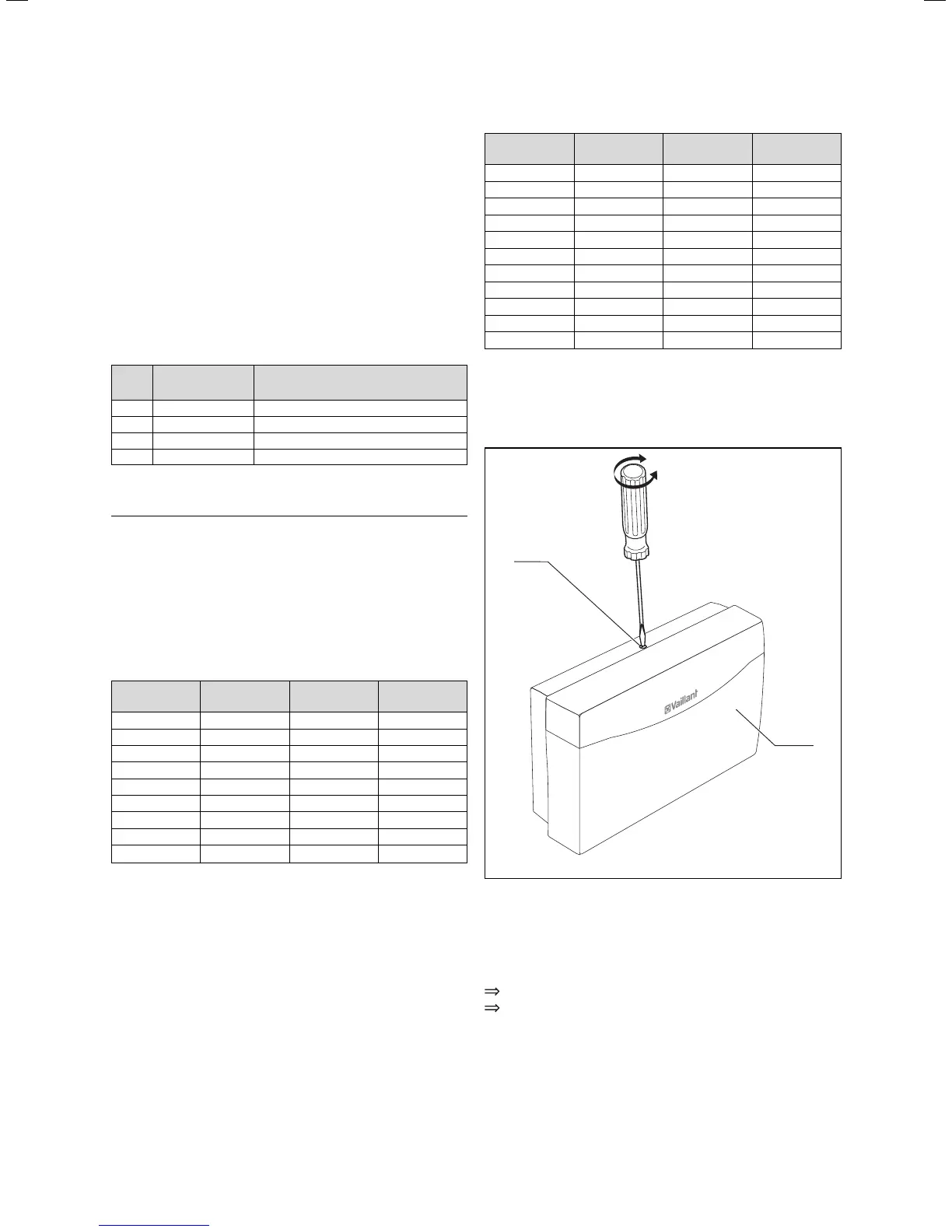
5.2 Mounting the VR 68 solar module
1
2
Fig. 5.1 Opening the casing
Key
1 Casing cover
2 Bolt
Unfasten the bolt (2) on the top of the casing.
Tilt the casing cover (1) forwards slightly and
remove it.
5 Assembly
 Loading...