17Operating and Installation Manual for Solar Module VR 68 0020054784_00
230 V~
PE N L
PE N L
PE N L
MA
KOL1-P
PE N L
LEG-P
+ -
BUS
2 1
KOL1
2
3
4
567
230 V~
5 V / 24 V
2 1
SP1
2 1
SP2
2 1
Ertrag
2 1
TD1
2 1
TD2
8
91011
M
1
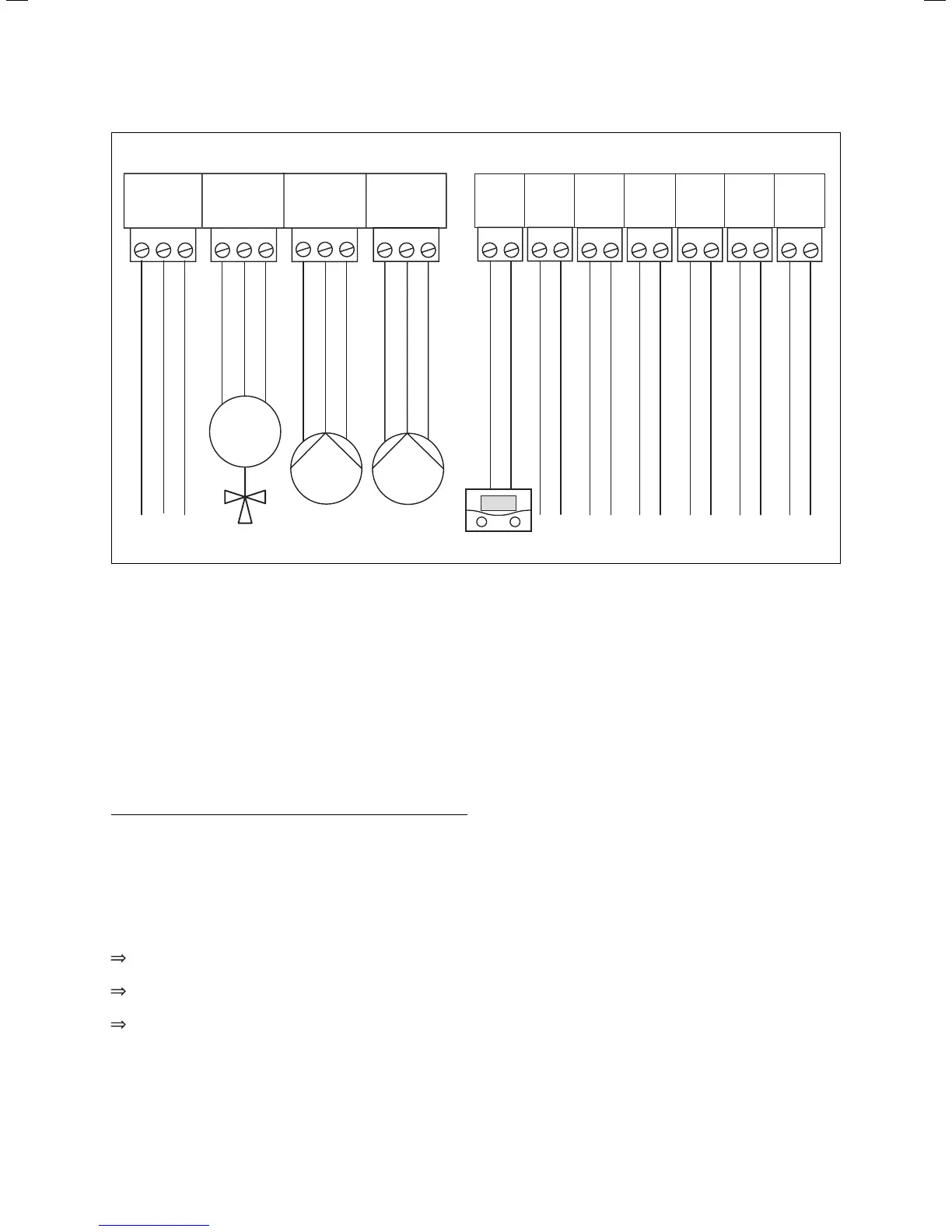
Fig. 6.2 Terminal assignment of VR 68 solar module
Key
1 Mains connection
2 Multifunction relays for swimming pool changeover valve or
additional differential control (restructuring, heating support)
3 Solar pump
4 Legionella protection pump
5 Connection, eBUS connection
6 Collector sensor 1
7 Cylinder sensor 1
8 Cylinder sensor 2
9 Sensor for yield measurement
10 Sensor TD 1 for swimming pool or additional differential control
11 Sensor TD 2 for additional differential control
h
Note!
If the VR 68 solar module is integrated into a
system with a VRC 430 or VRC 430f controller,
the multifunction relay is configured via the
installation assistant of the VRC 430 or
VRC 430f controller.
After connecting the electrical installation:
Secure all cables using the cable brackets provided
(see Fig. 5.2).
Reinsert the casing cover into the hinges at the
bottom and fold the casing cover up.
Screw on the casing cover as shown in Fig. 5.1.
Electrical installation 6
 Loading...