0020198787_01 Installation instructions 5
2 Notes on the documentation
2.1 Observing other applicable documents
▶ Always observe all the operating and installation instruc-
tions included with the system components.
2.2 Storing documents
▶ Pass these instructions and all other applicable docu-
ments on to the end user.
2.3 Validity of the instructions
These instructions apply only to:
VR 70 – article number
Great Britain
0020184844
3 Product description
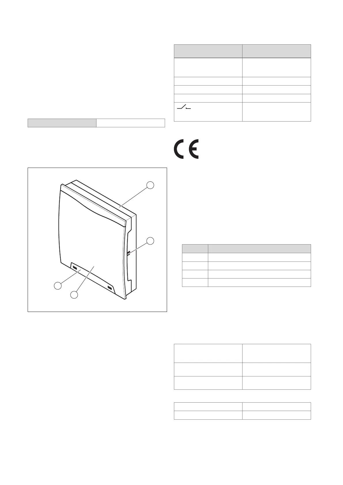
3.1 Design of the product
1 Wall-mounting base
2 Diagnostics socket
3 Front casing
4 Cover for the fixing
screw
3.2 Main function
The product has inputs and outputs. By assigning the inputs
and outputs in different ways, you can set up various sys-
tems. The inputs and outputs are configured using the sys-
tem control.
3.3 Data plate
The data plate is located on the right-hand side of the hous-
ing.
Information on the data
plate
Meaning
Serial number for identification; 7th to
16th digits = product article
number
VR 70 Product designation
V Operating voltage
W Power consumption
Switching capacity for each
relay and overall switching
capacity
3.4 CE marking
The CE marking shows that the products comply with the
basic requirements of the applicable directives as stated on
the declaration of conformity.
The declaration of conformity can be viewed at the manufac-
turer's site.
4 Set-up
4.1 Checking the scope of delivery
▶ Check that the scope of delivery is complete.
Quantity Component
1 VR 70
2 VR 10
1 Installation accessories (bolts and rawl plugs)
1 Documentation
4.2 Selecting the lines
▶ Use standard commercial lines for the wiring.
▶ Do not use flexible lines for mains voltage supply lines.
▶ Use insulation cables for mains voltage supply lines (e.g.
NYM 3 x 1.5).
Line cross-section
Supply line for mains
voltage (pump or mixer
mains cable)
≥ 1.5 mm²
eBUS line (extra-low
voltage)
≥ 0.75 mm²
Sensor line (extra low
voltage)
≥ 0.75 mm²
Line length
Sensor lines
≤ 50 m
Bus lines
≤ 125 m
 Loading...