0020198787_01 Installation instructions 7
Danger!
Risk of damage caused by incorrect in-
stallation.
Connecting wires that have been stripped
too far may cause short circuits and damage
the electronics if a strand accidentally comes
loose.
▶ Only strip the outer sheathing of flexible
ducts to a maximum of 2.5 cm to prevent
short circuits.
▶ Lay the lines correctly.
▶ Use the strain relief.
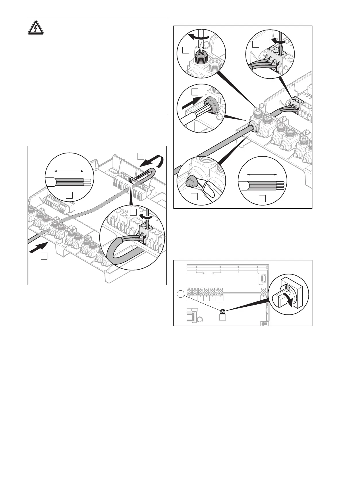
4. Strip the outer sheathing of the line, without damaging
the sheathing on the connecting wires.
Connecting the line to the upper terminal block
5. Push the line that is to be connected between the wall
and wall base to the upper terminal block.
6. Connect the required inputs and outputs in accordance
with the illustration.
7. Connect the eBUS line to the terminal block on the
PCB. In doing so, ensure that you comply with the po-
larity in the system.
Connecting the line to the lower terminal block
8. Connect all of the required lines in accordance with the
illustration.
9. Set the bus address. (→ Page 7)
10. Install the front casing. (→ Page 6)
5.2 Setting the bus address
BUS
-+
S2
12
S3
12
S4
12
S5
12
S6
12
S7
OI
1 Address switch
▶ Assign a unique address to each VR 70 that is connec-
ted, beginning with Address 1.
 Loading...