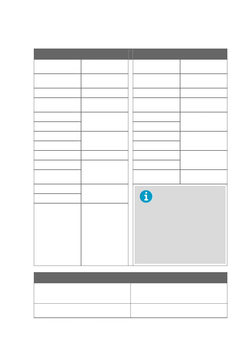
Writing Purge Interval Value
Request Response
Bytes on the Line
(Hexadecimal)
Description Bytes on the Line
(Hexadecimal)
Description
(silence for 3.5 bytes) Start of Modbus RTU
frame
(silence for 3.5 bytes) Start of Modbus RTU
frame
F0
hex
HPP272 address F0
hex
HPP272 address
10
hex
Function (Write
Multiple Registers)
10
hex
Function (Write
Multiple Registers)
03
hex
Register address 03
hex
Register address
08
hex
08
hex
00
hex
Number of registers to
write (1)
00
hex
Number of 16-bit
registers written (1)
01
hex
01
hex
02
hex
Number of data bytes 95
hex
Modbus RTU
checksum
0B
hex
Value for the register 6E
hex
40
hex
(silence for 3.5 bytes) End of Modbus RTU
frame
9B
hex
Modbus RTU
checksum
The response to a write
function informs that the
function was correctly received
by the device. It does not
guarantee that the written
value was accepted by the
device (for example, in case
out-of-range values).
To verify that the value was
really accepted by the device,
read the register value after
writing.
4C
hex
(silence for 3.5 bytes) End of Modbus RTU
frame
Communication Description
Register address 777 (1-based Modbus documentation format) =
0308
hex
(0-based format used in actual
communication).
Data format One 16-bit Modbus register interpreted as 16-bit
integer value.
Appendix A – Modbus Reference
59