23
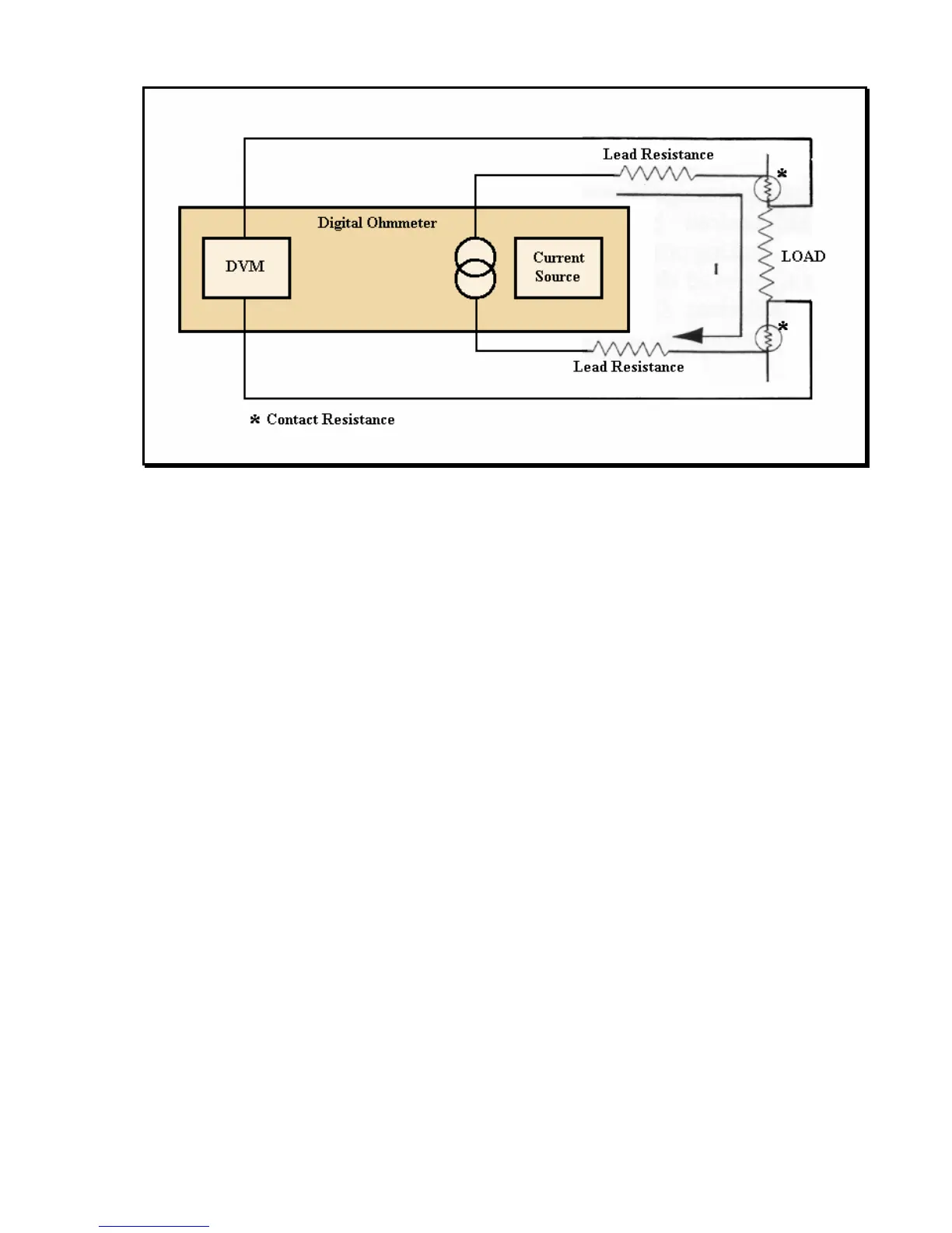
Figure 1 Error Sources in Resistance Measurements
4100ATC and 4150ATC Operations
The guidelines below should be followed for taking measurements using Models 4100ATC and
4150ATC:
1) Connect the test leads to the ohmmeter as described in the last section of this chapter.
2) Select the highest resistance range (20KΩ for 4100ATC or 2KΩ for 4150ATC).
3) Select the STD mode unless a compensator is attached to the connector on the front panel.
4)
Zero Adjustment. This adjustment may be performed at any time but does not need to be
performed before each measurement. To make the adjustment, select the 200Ω range and
connect the ohmmeter to a precision 0.1Ω resistor. Adjust the front panel ZERO
potentiometer so that the display indicates 000.10.
5) Connect the test leads to the load using a 4-wire configuration.
6) Select the most precise reading by downranging the ohmmeter until the display flashes
(indicating an overrange condition) and then moving back up one range.
NOTE: It is recommended that the ohmmeter be placed in the highest resistance range (far
right switch) prior to connecting or disconnecting the test leads to avoid drawing an
arc.