VALMAR Operation
Page 13
The green light indicates NORMAL rate and the
yellow light indicates ALT (alternate) rate.
Assembly procedures are contained in the
alternate rate kit itself.
Pressure Alarm
The red ALARM light and buzzer alerts the
operator to inadequate or excessive air manifold
pressure. The light and buzzer are activated by
the manifold pressure gauge. Refer to Manifold
Pressure Gauge in the Operation Section.
Figure 4 - 2: Control Unit
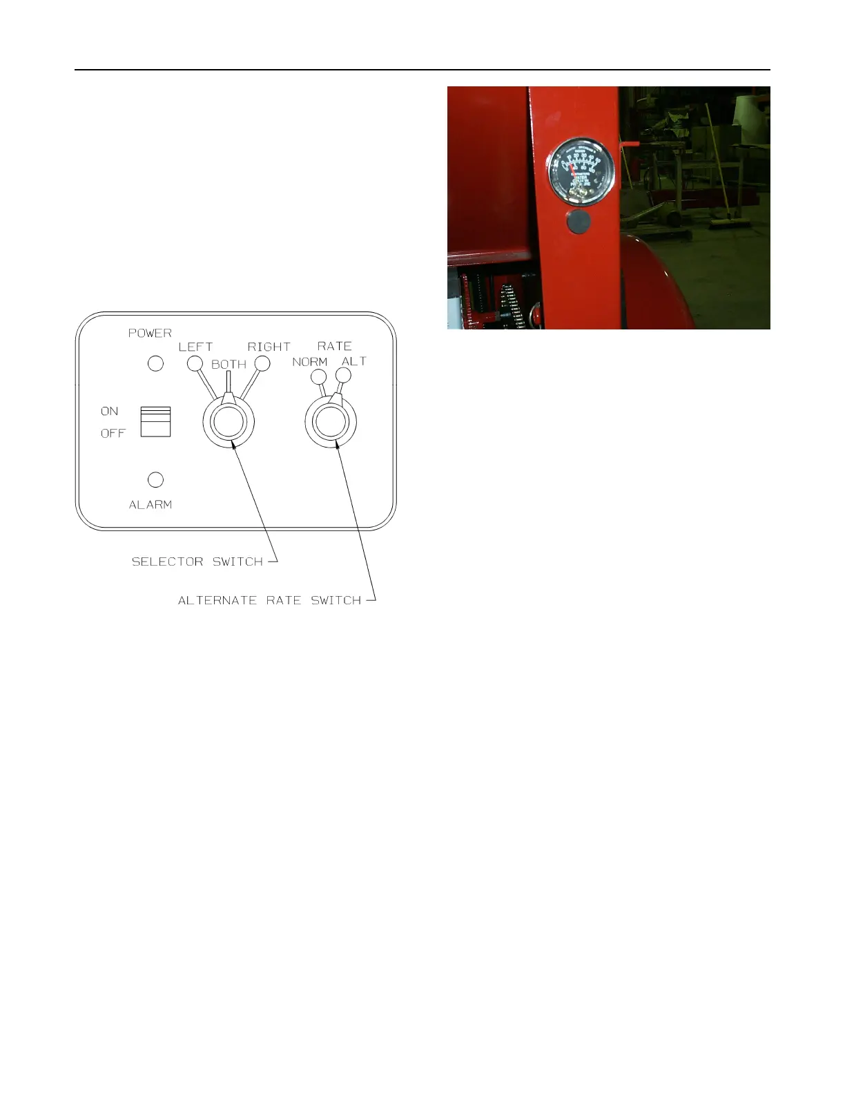
Manifold Pressure Gauge (Figure 4-2)
The manifold pressure gauge indicates proper
fan speed by measuring air pressure in the
manifold in inches (cm) of water column. The
pressure gauge includes a low pressure contact
set at 10 inches and a high pressure contact set
at 25 inches. The gauge is wired to the pressure
alarm light on the control unit. The pressure
alarm light will light up for two reasons:
1. The air pressure is below 10 inches.
2. The air pressure is above 25 inches.
Proper fan speed is achieved at a manifold
pressure of 17 inches of water column. Fan
speed is set by adjusting the speed of a gas
engine or a hydraulic motor which drives the
fan.
Figure 4 - 3: Pressure Gauge
Gas Engine Fan Drive (Optional)
The 2055 can be equipped with a 9 hp Honda
engine. The 2455 and 3255 can be equipped
with an 11 hp Honda engine.
Refer to the Honda Owner’s Manual for correct
startup and operation of the engine.
The engine is equipped with centrifugal clutch
that engages at 1600 rpm. Below that speed the
fan will not operate.
Hydraulic Fan Drive (Figure 4-4)
Operation of the hydraulic fan drive requires an
oil flow of 10.5 U.S. gpm for the 2055 and 2455,
and 11.5 U.S. gpm for the 3255.
The major components of the hydraulic fan
drive are:
1. the hydraulic motor for operating the fan.
2. The flow control valve for adjusting fan
speed.
There are two basic tractor hydraulic systems:
the Open Center system and Closed Center
System. Contact your tractor dealer to establish
which system you have. Set your fan speed as
follows:
 Loading...