Adjustments & Service Valmar
Clutches Do Not Release
The clutches should release when electrical
power is shut off. If metering rollers continue to
turn, inspect clutches for improper assembly.
Check the following:
1. Check bearings for corrosion, damage or
failure. They can cause the clutch to engage
improperly or drag.
2. Insufficient gap at clutch armature. If the
clutch armature contacts the rotor ring when
power is disconnected, add a spacer ring to
provide the 1/32 inch clearance between the
armature and rotor as indicated in the
diagram.
Clutches Do Not Engage
Raise ground drive wheel. Energize the
clutches by turning the control unit ON. Use
another 12 volt source if tractor is not attached.
Rotate wheel by hand and observe clutches to
see if they engage. If they do not engage
1. Check for electromagnetic attraction. Touch
the armature using a wrench or screwdriver
to see if it attracts metal. If there is no
magnetic pull, check the following:
a) Check the control unit. The Power
Switch must be ON. Check the
Normal/Alternate Switch to make
sure it is in the proper position.
b) Check the fuses to the control unit.
Refer to Fuses in this section.
c) Check connections to the power
source (battery).
d) Check all connections along
harness.
e) Check ohm resistant readout at
clutch. It should be between 2.4 and
2.8 ohms at room temperature.
2. There is magnetic pull, but no clutch
engagement. Check the following:
a) Check gap in the clutch. A gap
greater than 1/32 inch indicated in
Figure 6-1 means the spacer ring
should be removed.
b) If there is no spacer ring and gap is
greater than required, see your
Valmar dealer.
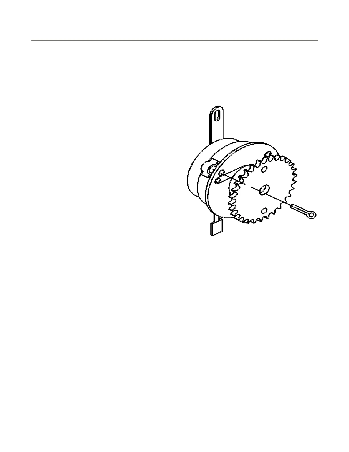
Clutch Lockup (Fig. 6-2)
Figure 6 - 2: Clutch Lockup
The electromagnetic clutches can be manually
engaged should an electrical failure by inserting
a 1/8” dia. pin through both clutch halves as
shown.
Gas Engine
Refer to the Honda engine Operator’s Manual
for correct engine maintenance procedures.
Centrifugal Clutch (Fig. 6-3)
The centrifugal clutch is secured to the engine
using Loctite 609. Should only the bearing
require replacement, do not remove the clutch
assembly from the engine output shaft. This will
prevent the breaking of the Loctite seal.
Bearing Replacement
The bearing can be replaced without removing
the clutch from the engine as follows:
 Loading...