EasyManua.ls Logo

Valmet SMART-PULP User Manual

Valmet SMART-PULP
44 pages
To Next Page IconTo Next Page
Page #1 background imageLoading...
Page #1 background image
BCs160VA
Nov. 15, 1997
SMART-PULP Smart Consistency Transmitter
Operating and Installation Instructions
Contents:
1 PUTTING INTO OPERATION
1.1 Mechanical installation
1.2 Electrical connections
1.3 Setting up the transmitter
2 TRANSMITTER FUNCTIONS (MENUS)
2.1 MEASUREMENT
2.2 CONFIGURATION
2.3 CALIBRATION
2.4 Sample taking and processing
3 SMART-PULP’S OPERATION AND
CONSTRUCTION
3.1 Construction
3.2 HART® communications
4 MAINTENANCE AND DIAGNOSTICS
4.1 Troubleshooting
4.2 Error messages
4.3 Checking the operation of force measurement
and current output
4.4 Adjusting the position of the display unit
4.5 Replacing the sensor blade
5 PARTS LIST
6 TECHNICAL SPECIFICATIONS
7 APPLICATIONS
7.1 Applications of different sensors
7.2 Materials for wetted parts
WARNING!
Before disconnecting or installing the
transmitter, ensure that the process pipe is
empty and depressurized. Observe the safety
instructions specified for the process.
HART® is a registered trademark of HART Communication Foundation.
We reserve the right for technical changes without prior notice.
Valmet Automation Inc., Measurements
PO Box 237, FIN-33101 Tampere, Finland
Tel +358 3 2668 111, Telefax +358 3 2668 448
Question and Answer IconNeed help?

Do you have a question about the Valmet SMART-PULP and is the answer not in the manual?

Valmet SMART-PULP Specifications

General IconGeneral
CategoryTransmitter
TechnologyMicrowave
Power Supply24 VDC
MaterialStainless steel
ApplicationPulp and paper industry
MeasurementConsistency
Measurement PrincipleMicrowave
Output Signal4-20 mA

Summary

1 PUTTING INTO OPERATION

1.1 Mechanical installation

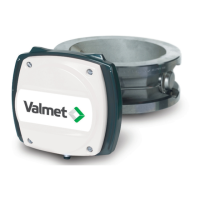
Details on physical installation and pipe requirements for the transmitter.

1.2 Electrical connections

Guide for wiring the transmitter, power supply, and connections.

1.3 Setting up the transmitter

Steps for initial configuration and calibration of the transmitter.

2 TRANSMITTER FUNCTIONS (MENUS)

2.1 MEASUREMENT

How to view measurement data like consistency and shear force.

2.2 CONFIGURATION

Defining application parameters, range limits, and units.

2.3 CALIBRATION

Procedures for calibrating the transmitter for different pulp types.

2.4 Sample taking and processing

Guidelines for collecting representative samples for calibration.

3 SMART-PULP'S OPERATION AND CONSTRUCTION

3.1 Construction

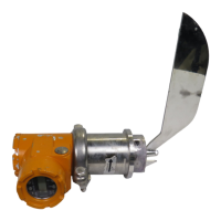
Detailed explanation of the transmitter's mechanical and electronic components.

3.2 HART® communications

How to use HART commands for transmitter configuration and control.

4 MAINTENANCE AND DIAGNOSTICS

4.1 Troubleshooting

Common faults, error messages, and corrective actions for operational issues.

4.2 Error messages

List and explanation of transmitter error messages and their severity.

4.3 Checking the operation of force measurement and current output

Procedures for checking and calibrating force measurement and output signals.

4.5 Replacing the sensor blade

Step-by-step instructions for replacing the sensor blade.

5 PARTS LIST

6 TECHNICAL SPECIFICATIONS

7 APPLICATIONS

7.1 Applications of different sensors

Guidance on selecting sensors based on pulp type and flow velocity.

Related product manuals