1 PUTTING INTO OPERATION
BCs160VA
Nov. 15, 1997
SMART-PULP Smart Consistency Transmitter
• The transmitter must be mounted at 90
O
angle to
the pump axis and on the side of the line indicated in
Figure 1.1.1a, i.e. on the side where the pulp is
discharged from the pump.
NOTE! The direction of a pipe bend downstream
from the transmitter has no effect.
WARNING !
Before installing the process coupling, make
sure that the process line is empty and
depressurized !
1.1 MECHANICAL INSTALLATION
1.1.1 Points of importance in installation
• The pipe’s inside diameter must be at least 100
mm, and flow velocity must be as shown in the
APPLICATION chapter. If required, the pipe
diameter can be altered so as to achieve the desired
flow velocity.
• Pulp flow must be laminar.
• The pipe should have sufficiently long straight
sections of uniform diameter both upstream and
downstream from the transmitter (Fig. 1.1.1a).
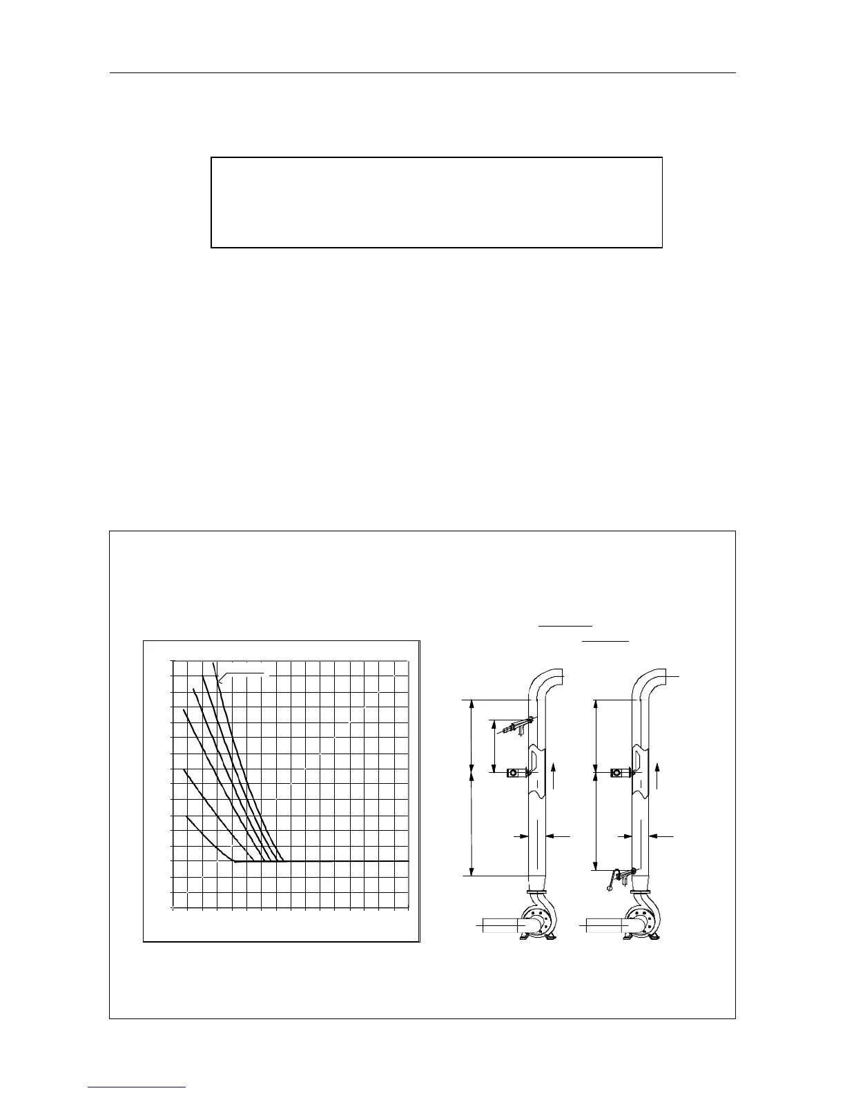
Figure 1.1.1a Determination of coefficient k as a function of pulp consistency and flow velocity
(see Fig. 1.1.2a)
2
0
1
2
3
4
5
6
7
8
9
10
11
12
13
14
15
16
012345678910111213141516
Minimum lengths of straight pipe sections:
L
1min
= k x D; L
2min
= 0.3 x L
1min
+ 250 mm
v = 5 m/s
0.5
1
2
4
3
k
Consistency %
SMART-
PULP
SMART-
PULP
NOVE
pneum
NOVE
manual
Example
D = 250 mm, Cs = 3 %, v = 2 m/s
L
1min
= 8.5 x 250 = 2125 mm
L
2min
= 0.3 x 2125 + 250 = 887 mm
L
2
L
2
D
L
1
L
1
400
D