110
Model Code Page
33. Agroline ---instrument
1. 9. 2002
333 6
6200--8950Hi
3. Others
Changing speed and distance units
(km/h---miles/h)
The units have been set in the facto ry for various market
areas. In Service t he units cannot be changed.
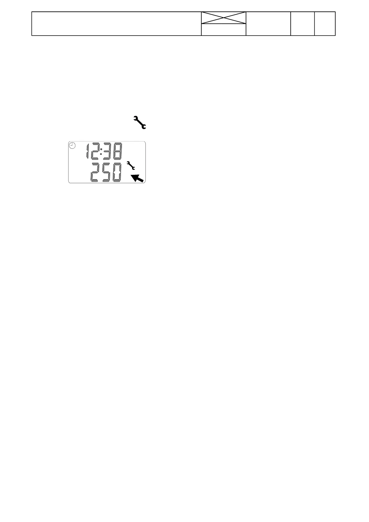
Indication of periodical maintenance:
Note! When the tr actor running hours reach a service inter-
val, a spanner symbol and the running hours of the service
interval in question come on into the diplay.
If the service is not done, the spanner and the service inter-
val are visible for 10 seconds every time the ignition is
switched on.
The Service man (or customer) can confirm that the main-
tenance has been done by pressing switch (30)leftedge
and at the same time switching on the ignition. After this the
spanner symbol is not visible until the next Service is ap-
proaching.
4. Fault codes
Agroline---instrument can show fault codes for a damaged
sensor, at which t i me the spanner symbol is visible in the
display.
The fault code can be seen by scanning with switch (30).
The fault code is shown in the upper row of the display
(17), if one of the following sensors have a malfunction or
wires have problems:
--- fuel level sensor B2. First digit of three ---number code.
--- engine temperature sensor B1. Middle digit of fault
code.
--- gearbox temperature sensor B3. Last digit of fault code.
0=OK
1= poor contacts or too high resistance
2 = sho rt circuit or too low res istance
E.g: 200: fuel senso r short circuit
E.g: 010: engine temperature sensor resistance too high
(wire broken, sensor damage etc.).
E.g: 001: gearbox temperature sensor resistance too high
(wire broken, sensor damage etc.).
Fault tracing:
--- If the Agroline ---instruments have malfunctions, check
that the instrument rear face connectors X26 and X27 are
correctly connected. If the instrument is totally black al-
though t he current is switched on, check the fuses F14
(ignition switch) and F18 (instrument), supply wires and
earth points. (See wiring diagrams on pages 310/105,
Mezzo/Mega and 310/93, HiTech). The position of different
components and connectors can be found on page
310/6C, (Mezzo/Mega) and 310/6E, (HiTech).
--- When necessary, check various sensors and switches
acco rding to instructions 5 and 6.Ifwires,switchesand
senso rs are OK, but the problem still exist, change the in-
strument.
--- S w i t c h ( 30) earths in the instrument rear face pins no 24
and 25 of the connector X26, when different edges of
switch are pressed.
If the instrument does not respond to the use of these
switches, check wire joints in the switches and instrument
connec tors behind the instrument. If these are OK, the fault
can lie inside the instrument.