O&M-V5-FAP-AVF-LCD R0
Operator’s Manual (Fire Alarm Panel c/w AVF & LCD)
Pg 17 of 21
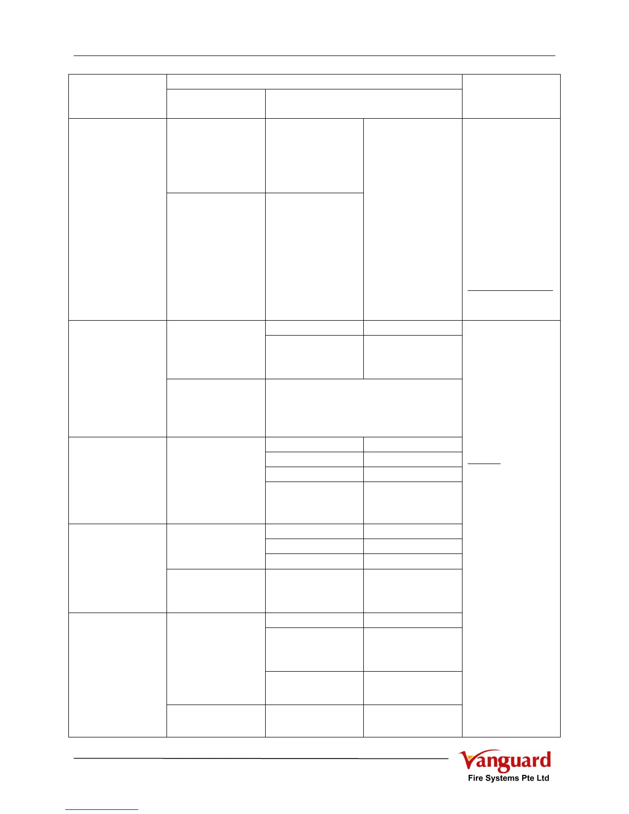
CHECK LIST
FAULT
Specific
Indication
Possible Causes
ACTION SHOULD
BE TAKEN
Earth “+VE” (Red)
(@ FBM)
- One or more Field
“+VE” line and/or
- Alarm “–VE” line
(in normal condition)
Earth Fault
Earth “-VE” (Amber)
(@ FBM)
- One or more Field
“-VE” line and/or
- Alarm “+VE” line
(in normal condition)
- Shorted to Chassis /
Trucking / Conduit
1. Press “Buzzer
Silence” (Black-1)
2. Dismantle all the
Line accordingly with
proper marking
3. Terminate back the
lines one by one to
trace the faulty lines
4. Rectify the fault.
5. When fault is clear,
back to normal
If unable to normalise
1. Call for service
- Aux Fuse - Blown “Aux Fuse” (Amber)
(@ FBM)
- Auxiliary Output - Over loaded
- Line shorted
Auxiliary Fault
Alm-2 “O” / “S”
(@ FBM)
- Alarm-2 output is used for Auxiliary
(Option as provided)
- Refer to “Sounder Fault” for fault finding
- AC 230V Mains - Failure
- AC Fuse - Blown
- AC Switch - OFF position
Mains Failure
Charger Fault
- “Mains Failure”
(Amber)
- “Charger Low /
Fuse” (Amber)
(@ PSM)
- Termination - Loose
- Charger Fuse - Blown
- System total load - Over loaded
“Charger Low /
Fuse” (Amber)
(@ PSM)
- System Voltage - Low < 21V
Charger Fault
“CH/BAT High” (Red)
(@ PSM)
- System Voltage - High > 30V
- Battery Fuse - Blown
- Termination - Loose
- Cable shorted
- Connection Reversed
“Battery Low / Dis.”
(Amber)
(@ PSM)
- Battery - Low > 21V
- Faulty
Battery Fault
“CH/BAT High” (Red)
(@ PSM)
- System Voltage - High > 30V
1. Press “Buzzer
Silence” (Black-1)
2. Check the possible
causes and rectified
3. When fault is
rectified, back to normal
If unable to normalise
1. Call for servicing
Remark:
1. Fuse shall be
replaced with Rated
Fuse as accordingly.
2. System normal
operating voltage shall
be DC 27.5V.
(Adjustable by VR1 @
PSM)