O&M-V5-FAP-AVF-LCD R0
Operator’s Manual (Fire Alarm Panel c/w AVF & LCD)
Pg 5 of 21
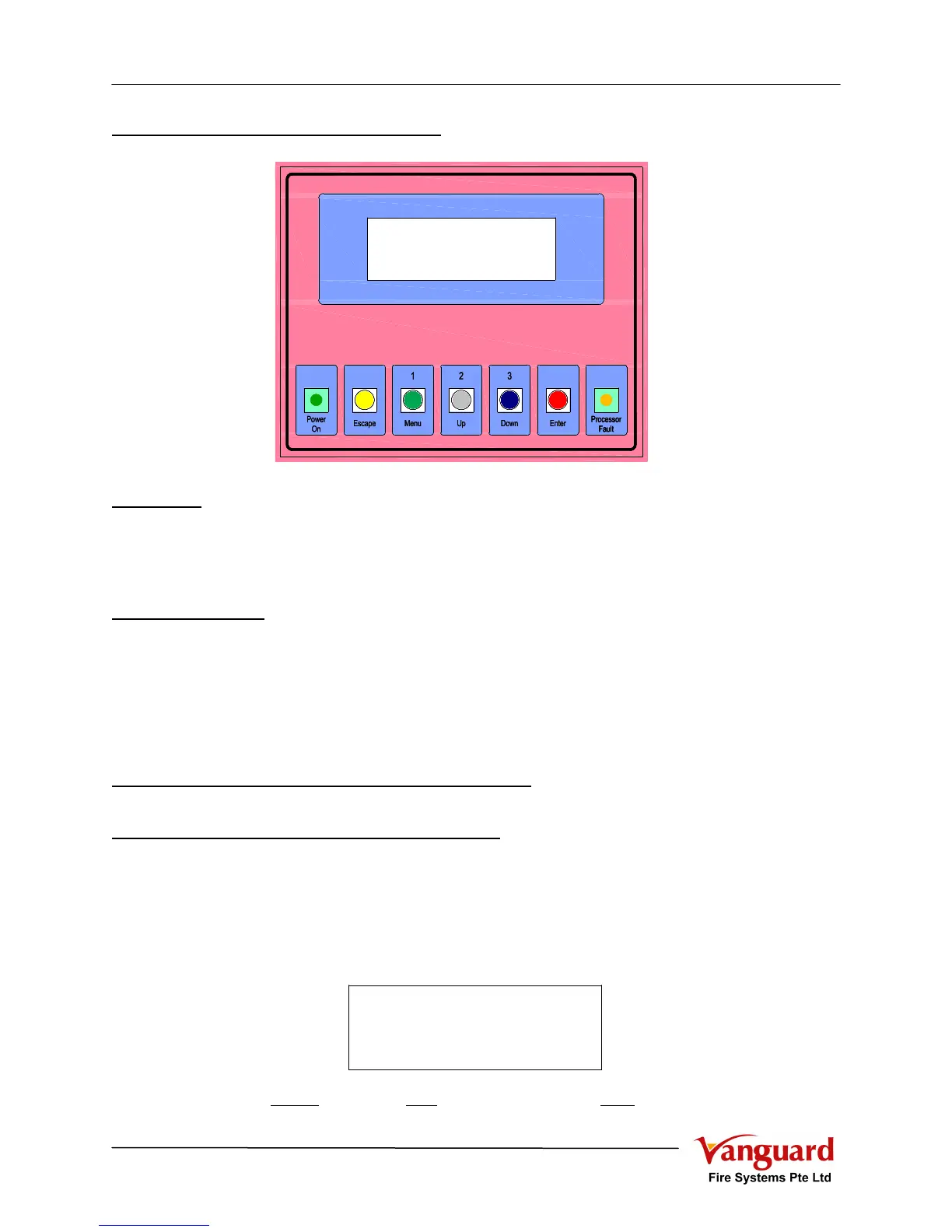
1.2.3 LCD Event Logging Module
Indicators
a) Power On (Green) : System energised by Mains and/or Standby Battery
b) Processor Fault (Amber): Indicates that Micro Processor Unit failure in processing
c) LCD Display : To display the Panel Status and the Alarm / Fire event c/w
date and time (20 Characters x 4 Lines)
Control Switches
a) Escape (Yellow) : To exit from current function / screen
b) Menu (1) (Green) : To access other level of function or password key as “1”
c) Up (2) (White) : To move cursor up / page up or password key as “2”
d) Down (3) (Blue) : To move cursor down / page down or password key as “3”
e) Enter (Red) : To select / accept the function / setting
2. OPERATING INSTRUCTIONS
2.1 Normal Operating Conditions
Under normal operating conditions
a) The “POWER ON” LED (Green) lighted
b) No other indicator shall be lighted
c) The panel and all alarms should be completely silent
d) LCD display shown as
(07/04/06: 7
th
April 2006, M000: “Main” panel address “000”, 20:06: 8:06PM)
LCD Event Logging Module - LLMLCD Event Logging Module - LLM
FIRE ALARM SYSTEM
07/04/06 M000 20:06
FIRE ALARM SYSTEM
07/04/06 M000 20:06