O&M-V5-FAP-AVF-LCD R0
Operator’s Manual (Fire Alarm Panel c/w AVF & LCD)
Pg 21 of 21
1
Z1
+ -
2
-+
Z2
3 4
-+
Z3
5 6
-+
Z4
7 8
-+
Z5
9 10
-+
Z6
11 12
-+
Z7
13 14
-+
Z8
15 16
-+
ALM-1
17 18
-+
ALM-2
19 20
C+ NC-
AUX-1
21 22 23
NO- C+
AUX-1
24
NO-NC-
25 26
3
C
FIRE
+ -
TO MAP
1 2
NC NOCNONC
FAULT
864 5 7 109
++
1211
--
1413
G-ALM
IPOP
1615
G-SIL
IPOP
1817
G-RST
IPOP
2019
G-AUX
IPOP
AUX - DC 24V
VC
FC
AUX-1
1
2
3
FC
VC
1
3
2
AUX-2
ALM-1 ALM-2 AUX
FUSES
MAP
SAP
G-RST
JS1
ZONE FUSE
BELL
AUX
ALM-2
+ - CO
JS2
EARTH
+VE -VE OS
ALM-1
OS
ALM-2
+ - CO
CO - +
AC AC
OFF
ON
SW1
24V DC
+ -
BATTERY
BATTERY FUSE
CHARGER FUSE
VR1
Vanguard
V5-PSM-1
Vanguard
V5-FBM-1
N E L
AC 230V
MAIINS
Fuse
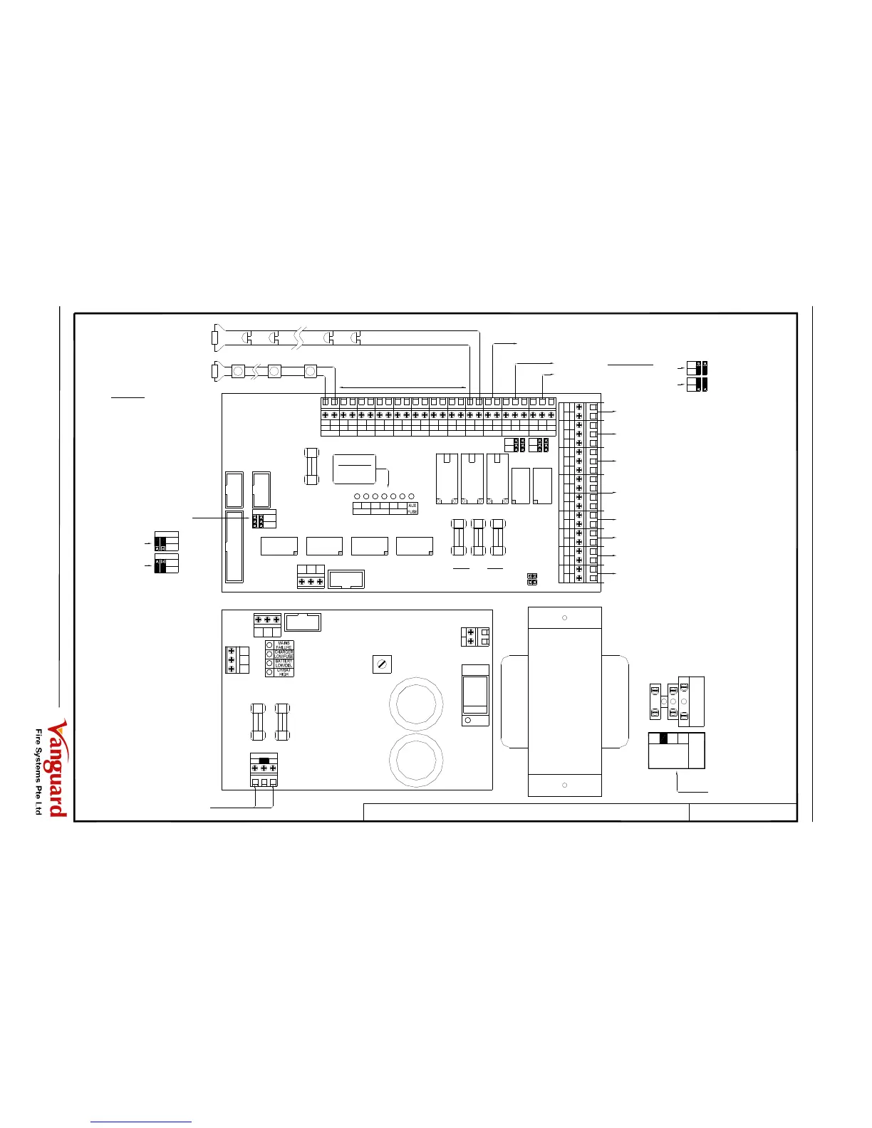
EOLR
6K8 OHM
DETECTORS / CALLPOINTS
POLARISED SOUNDERS / BELLS
6K8 OHM
As (Z1) Connection
As ALM-1 Connection
Auxiliary Output-1
Auxiliary Output-2
}
As per Jumper Setting
(1,2) FC = Free Contact Output
Signal to Main Alarm Panel (MAP) Zone
Common FIRE Output
(Free Contact)
Common FAULT Output
(Free Contact)
DC 24V
Constant Supply Output
For General Alarm Signal
For General Sounder Silence Signal
For General Reset Signal
For General Auxiliary Signal
Transformer
24V DC Standby Battery
AC 230V Mains Supply
LEGEND:
EOLR
EOLR = End Of Line Resistor
(Shall be placed at last device)
Jumper Setting for ALM-2 output
to operate as BELL or AUXILIARY function
LEGEND:
S = Line Short
O = Line Open
Filename:
(2,3) VC = Voltage Contact Output
FC
VC
1
3
2
FC
VC
1
3
2
BELL
BELL
AUX
ALM-2
AUXILIARY
BELL
AUX
ALM-2
V5-FBM-1-TIL
Title:
Typical terminal installation layout of Fire Base Module (V5-FBM-1)
TB3
TB2
 Loading...