Do you have a question about the Varian Micro-GC 490-GC and is the answer not in the manual?
Warranty terms for physical analytical instruments and their components.
Warranty conditions for software provided under license agreements.
Describes exclusive remedies for hardware warranty claims, including repair or replacement.
Outlines exclusions from warranty coverage, including consumables and misuse.
States provided remedies are exclusive and limits liability for damages.
Details CE specifications, safety requirements, and regulatory compliance.
Guidance on using the manual and understanding safety precautions.
Explains common warning symbols (caution, danger, burn hazard) and their meanings.
Practices for safe operation, including handling gases and waste.
Specific safety advice, including electrical hazards and proper cord usage.
Information on obtaining spare parts and available post-warranty service options.
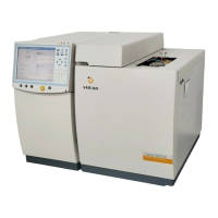
Welcome to the Varian Micro-GC, highlighting EGC technology and its benefits.
Specifications for carrier gas quality and sample preparation.
Guidelines for preparing and introducing gaseous samples to the instrument.
Steps for inspecting the instrument upon arrival and unpacking it safely.
A detailed list of all items included in the Micro-GC package.
List of optional accessories available for the Micro-GC system.
Instructions for installing and setting gas regulators for optimal pressure.
Details on connecting the carrier gas supply to the instrument.
Connecting workstations and other data acquisition devices.
How to connect the sample inlet to the instrument.
Guide for connecting heated sample lines for specific analyses.
Steps for electrical hookup and turning the instrument on for the first time.
Information on the instrument's default configuration upon shipment.
Identifies and explains the indicators and controls on the front panel.
Details the connectors, vents, and ports located on the rear of the instrument.
Shows internal connectors and ports accessible after opening the cover.
Specifics on connecting carrier gas, including tubing and filter recommendations.
Advice on preparing gaseous samples and using external filters.
Configuration for analyzing samples using heated injectors.
Procedure for connecting the heated sample line, including safety warnings.
Details on the instrument's power needs and safety during operation.
Steps for safely powering down the instrument for short or long periods.
Steps to follow when recovering the instrument after extended storage.
Guide to entering method parameters and sending them to the instrument.
How to connect and introduce samples for analysis.
Chromatogram and parameters for the CP-SIL 5 CB 6m unheated column.
Chromatogram and parameters for the CP-SIL 5 CB 4m heated column.
Chromatogram and parameters for the CP-SIL 5 CB 8m heated column.
Chromatogram and parameters for the CP SIL13CB TBM 12m heated column.
Chromatogram and parameters for the HayeSep 40cm heated column.
Chromatogram and parameters for the Molsieve 5Å 20m unheated column.
Method to restore Molsieve column efficiency by heating and purging.
Chromatogram and parameters for the PPQ 10m heated column.
General description of the Micro-GC's components and modules.
Details on carrier gas types, purity, and pressure requirements.
Explanation of the EGC system for precise pressure and flow control.
Overview of different column types and their suitability for various analyses.
Description of the Thermal Conductivity Detector (TCD) and DMD.
Information on the instrument's input and output connection ports.
Details on digital input and output connections for external devices.
Overview of serial (RS232/RS485) and Ethernet communication ports.
Details on external analog input and output connections.
Guidelines for preparing the instrument for return shipment to the factory.
Recommendations for safely cleaning the exterior of the Micro-GC.
Information on proper disposal of the instrument according to regulations.
Introduction to the DMD, including safety precautions related to its radioactive source.
Explanation of how the DMD operates using ion mobility spectroscopy principles.
Location and recognition of the DMD channel within the Micro-GC system.
How the DMD is managed by workstation software and its specific settings.
Procedure for optimizing DMD performance through tuning runs.
Lists various communication protocols used in networking.
Information on TCP/IP, its development, and related services.
Explains IP addresses, their format, and range for network identification.
Specifies cable types, network compliance, and hardware for Micro-GC networking.
Answers common queries regarding connecting the Micro-GC to a network.
Definitions of essential networking vocabulary for clear understanding.
Details on patch cables, RJ45 connectors, and the TCP/IP protocol.
Configuration for EZChrom Elite and Galaxie, including COM ports and IP setup.
Settings for integrating analog and digital I/O with workstation software.
How to configure relay control functions within the software.
Methods for controlling the Micro-GC via serial or Ethernet connections.
Instructions for establishing a serial connection to the instrument.
Setting up a direct Ethernet connection between a computer and the Micro-GC.
Connecting multiple instruments to a local network via a switch.
Connecting instruments across multiple networks using routers.
Detailed steps for configuring communication parameters for control.
Procedure to assign a new IP address to the Micro-GC over Ethernet.
Procedure to assign a new IP address using a serial connection.
How to access instrument status and parameters remotely.
UserDataStore addresses for instrument parameters and analog inputs.
Classification of error classes (diagnostic, advisory, critical, fatal).
How the Micro-GC reacts to events and error messages.
Detailed error codes, descriptions, and actions for errors 1-28.
Detailed error codes, descriptions, and actions for errors 29-60.
Detailed error codes, descriptions, and actions for errors 61-999.
Explanation and diagrams of backflush to vent technique for column maintenance.
Method for adjusting backflush time to optimize analysis and column condition.
Explanation of special values for backflush time, including FOREFLUSH mode.
| Brand | Varian |
|---|---|
| Model | Micro-GC 490-GC |
| Category | Laboratory Equipment |
| Language | English |


 Loading...