Installation, Operating & Maintenance Instructions
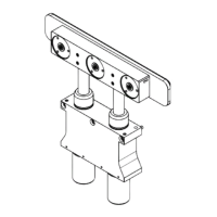
Series 264, DN 10 - 16 (I.D. 3/8 - 5/8")
VAT Vakuumventile AG, CH-9469 Haag, Switzerland
Tel +41 81 771 61 61 Fax +41 81 771 48 30 CH@vatvalve.com www.vatvalve.com
279114EC
2010-10-06
6/10
3.3.1 Safety Low Voltage Control (20 .. 28 V DC)
21
3
23451
9876
The valve requires system voltage supply at the power connector (100 .. 115 VAC or 200 .. 240 VAC - check label on
valve). On the signal connector provide 20 .. 28V DC to the micro controller according to the wiring diagram to pins 5-6.
Operation:
• To open the valve, power has to be provided to pins 5 and 6
• To close the valve, power has to be switched off for pins 5 and 6
Position Indicator:
The solid state relays indicate the valve position as long as power is provided to the power connector. In addition the
LED’s indicate the position of the valve (green for valve open; orange for valve closed)
3.3.2 Line Voltage Control (100 .. 240 V AC) without Position Indicator
21
3
Valves are available for 100 .. 115 VAC and 200 .. 240 VAC (check label on valve).
Operation:
• To open the valve, power has to be provided to N and both L and L’.
• To close the valve, power has to be switched off for L’ and L.
Position Indicator:
The green LED will indicate the open valve position. After switching off the power, the orange LED might indicate the
closed valve position, but the light will fade out shortly afterwards.
Note: This connection diagram can be used to replace valves in case no L’ signal is available.
 Loading...