EasyManua.ls Logo

VAT 264 Series - User Manual

VAT 264 Series
10 pages
Print Icon
To Next Page IconTo Next Page
Loading...
Installation, Operating & Maintenance Instructions
Series 264, DN 10 - 16 (I.D. 3/8 - 5/8")
VAT Vakuumventile AG, CH-9469 Haag, Switzerland
Tel +41 81 771 61 61 Fax +41 81 771 48 30 CH@vatvalve.com www.vatvalve.com
279114EC
2010-10-06
1/10
HV-Angle Valve (Series 264)
HV-Inline Valve
(Series 265)
with electromagnetic actuator
single acting with closing spring (NC)
This manual is valid for the valve ordering number(s):
26...
The fabrication number is indicated on each product as per the label
below (or similar):
made in S witzerland
Fabrication No.:
patente d
. .
26
. . .
. . . .
A
. . . . . .
Fabrication number
Explanation of symbols:
Read declaration carefully before you start any other
action!
Keep body parts and objects away from the valve
opening!
Attention!
Hot surfaces; do not touch!
Product is in conformity with EC guidelines,
if applicable!
Loaded springs and/or air cushions are potential
hazards!
Disconnect electrical power and compressed air
lines. Do not touch parts under voltage!
Wear gloves!
Read these «Installation, Operating & Maintenance Instructions» and the enclosed «General
Safety Instructions» carefully before you start any other action!
A
A .. Aluminum E .. Stainless Steel
20.. DN 10 24 .. DN 16
4 .. Angle Valve 5 .. Inline Valve
-K
61
24
4
26
K .. ISO-KF G .. CF-R

Questions and Answers

Overview

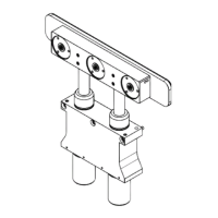
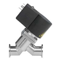
This document provides installation, operating, and maintenance instructions for the VAT Series 264 HV-Angle Valve and Series 265 HV-Inline Valve. These are vacuum valves equipped with an electromagnetic actuator, designed for single-acting operation with a closing spring (normally closed - NC).

Function Description:

The valves are designed for clean and dry indoor vacuum applications. They operate by an electromagnetic actuator that, when energized, opens the valve, and when de-energized, allows a closing spring to return the valve to its normally closed position. The control can be either Safety Low Voltage (20-28 V DC) or Line Voltage (100-240 V AC), with or without a position indicator. The position indicator, when present, uses solid-state relays and LEDs (green for open, orange for closed) to show the valve's status. In case of a power failure, the valve automatically closes, and both position indicator relays open with LEDs off.

Important Technical Specifications:

  • Leak Rate: < 1 x 10⁻⁹ mbar l s⁻¹ (for FKM-Seals).
  • Pressure Range: 1 x 10⁻⁸ mbar to 2 bar (absolute).
  • Differential Pressure on Plate: ≤ 2 bar.
  • Closing Time: ≤ 0.2 seconds.
  • Admissible Temperature: 0-50°C.
  • Maximum Operating Frequency: 15 cycles per minute at 20°C.
  • Cycles until first service: 200,000.
  • Mounting Position: Any.
  • Voltage: 100-115 VAC or 200-240 VAC; 50/60 Hz for line voltage control, and 20-28 V DC for safety low voltage control.
  • Power Consumption: Pick up 700 W (~100 ms), Holding 10 W.
  • Position Indicator Contact Rating: Max. 48 V AC/DC; max 500 mA.
  • Protection Class: IP 40.
  • Overcurrent Protection Device: 2 A, tripping characteristic "D" (EN 60898).
  • Materials:
    • Valve Plate: AISI 316L (1.4404, 1.4435).
    • Bellows: AISI 316L (1.4404, 1.4435), 316 Ti (1.4571).
    • Seals: FKM (VITON) (others optional according to dimension drawing).
    • Body (Aluminum valve): EN AW-6060 (3.3206), EN AW-6061 (3.3211), EN AW-6063 (3.3206), EN AW-6082 (3.2315).
    • Body (Stainless steel valve): AISI 304 (1.4301, 1.4305).
  • Molecular Flow Conductance: DN10: 3 l/s; DN16: 5 l/s.
  • Weight:
    • Aluminum Angle Valves: 1.3 kg (2.9 lbs).
    • Aluminum Inline Valves: 1.3 kg (2.9 lbs).
    • Stainless Steel Angle Valves: 1.3 kg (2.9 lbs).
    • Stainless Steel Inline Valves: 1.4 kg (3.1 lbs).
  • Axial Tensile or Compressive Force (FA): 25 N (6 lbf) for both DN10 and DN16.
  • Bending Moment (M): 1 Nm (0.8 lbf.ft) for both DN10 and DN16. A combination of both FA and M is prohibited.

Usage Features:

  • Installation: The valve should be unpacked carefully, ensuring no damage. Plastic packing material and protective covers should only be removed immediately before mounting. Sealing surfaces must be handled with care and kept clean. Electrical power should only be connected once the valve is installed in the system and moving parts cannot be touched.
  • Control:
    • Safety Low Voltage Control (20-28 V DC): To open the valve, power must be provided to pins 5 and 6 of the signal connector. To close, power must be switched off for pins 5 and 6.
    • Line Voltage Control (100-240 V AC) without Position Indicator: To open the valve, power must be provided to N and both L and L' of the power connector. To close, power must be switched off for L' and L.
    • Line Voltage Control (100-240 V AC) with Position Indicator: To open the valve, power must be provided to N and both L and L' of the power connector. To close, power must be switched off for L'.
  • Position Indicator: For models with position indicators, solid-state relays indicate the valve position as long as power is supplied to the power connector. LEDs provide a visual indication (green for open, orange for closed).
  • Safety: The valve should only be installed by a trained professional according to local technical standards and law. Connecting cables must not exceed 30 m in length. The coil can reach temperatures of up to 70°C during continuous use, so caution is advised when touching.
  • Troubleshooting: A table is provided to address common issues such as the valve not operating (check installation, power, cycle frequency) or flashing position indicators (check cycle frequency, interference with valve movement).

Maintenance Features:

  • Under clean operating conditions, the valve does not require maintenance during its specified cycle life. However, contamination from the process may necessitate more frequent maintenance.
  • Before any maintenance or repairs, VAT should be contacted to determine if the work can be performed by the customer or requires VAT service. The fabrication number (found on the valve's label) must always be specified.
  • All supplies (e.g., compressed air, electrical power) must be disconnected before removal/installation or maintenance.
  • Even with disconnected supply, loaded springs and/or air cushions in cylinders can pose potential hazards. Fingers and objects must be kept away from the valve opening.
  • Products returned to VAT for service must be free of harmful substances. If radioactively contaminated, a specific VAT form ("Contamination and Radiation Report") must be filled out and sent with the product.
  • Seal Replacement Procedure: Detailed steps are provided for replacing seals, including removing connectors, screws, coil assembly, bonnet screws, and the valve insert. It emphasizes careful handling of sealing surfaces, cleaning, and uniform reassembly of new O-rings and components.
  • Spare Parts: A drawing with item numbers is included for ordering spare parts. Key spare parts include the Seal Kit (items 61, 62, 63) and the Coil with Electronics (item 26). The fabrication number of the valve must be specified when ordering spare parts to ensure compatibility.
  • Warranty: VAT warrants products to be free from manufacturing defects during the warranty period stated in VAT's "Terms of Sale," provided proper operation, regular maintenance, and service are performed. The warranty does not cover products repaired or altered by unauthorized personnel, or those subjected to improper installation, abuse, misuse, negligence, or accident. The exclusive remedy for defects is repair or replacement at VAT's factory, at no charge.

VAT 264 Series Specifications

General IconGeneral
BrandVAT
Model264 Series
CategoryController
LanguageEnglish

Related product manuals