Installation, Operating & Maintenance Instructions
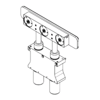
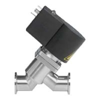
Series 264, DN 10 - 16 (I.D. 3/8 - 5/8")
VAT Vakuumventile AG, CH-9469 Haag, Switzerland
Tel +41 81 771 61 61 Fax +41 81 771 48 30 CH@vatvalve.com www.vatvalve.com
279114EC
2010-10-06
7/10
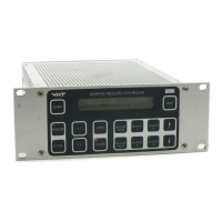
3.3.3 Line Voltage Control (100 .. 240 V AC) with Position Indicator
21
3
23451
9876
Valves are available for 100 .. 115 VAC and 200 .. 240 VAC (check label on valve).
Operation:
• To open the valve, power has to be provided to N and both L and L’.
• To close the valve, power has to be switched off for L’.
Position Indicator:
The solid state relays indicate the valve position as long as power is provided to the power connector. In addition the
LED’s indicate the position of the valve (green for valve open; orange for valve closed)
3.3.4 Operation under increased temperature
See «2 Technical data»
Attention!
Coil of magnet can reach a temperature of 70° C when continuously used. Beware of touching!
3.4 Behavior in case of power failure
Valve closes
Both position indicator relays are open, LEDs are off.
4 Trouble shooting
Failure Check Action
Valve does not operate Confirm correct installation Install valve correctly
Confirm correct power on connectors Provide correct power
Position Indicator are flashing
alternant
Check cycle frequency of the valve Wait, valve will operate as soon as
frequency is in correct range
Check if valve movement is interfered
by any object
Remove object and clean valve
If you need any further information, please contact one of our service centers. You can find the addresses on our website:
http://www.vat.ch
 Loading...