EasyManua.ls Logo

VAT 64.1 Series - User Manual

VAT 64.1 Series
20 pages
Print Icon
To Next Page IconTo Next Page
Loading...
c
e
r
t
i
f
i
e
d
Q
M
-
S
y
s
t
e
m
g
e
p
r
ü
f
t
e
s
Q
M
-
S
y
s
t
e
m
ISO 9001
EN 29001
Installation, Operating, and Maintenance Instructions
Series 64.1
VAT Vakuumventile AG, CH-9469 Haag, Schweiz
Tel ++41 81 771 61 61 Fax ++41 81 771 48 30 Email reception@vat.ch http://www.vatvalve.com
283681EB
2011-03-18
1/19
Adaptive Pressure Controller
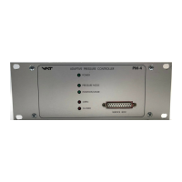
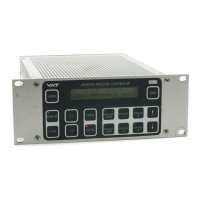
PM-4 & 5 for Gate Valve Control System
This manual is valid for product with the
product identification number
FABR. NO. 641PM - . 6 . . - . . . .
configured with Software Version
64PM.3I.00
The product identification is specified on the rear panel of each PM controller:
Made in Switzerland in 20 . .
Patented
641P . - . 6 . . - . . . . - . . . .
Read these «Installation, Operating and Maintenance Instructions» (IOMI) and the enclosed
«General Safety Instructions» carefully before you start any other action.
Table of content
1 Intended Use of Product..........................................................................................................................2
1.1 Technical Data.................................................................................................................................2
2 Installation...............................................................................................................................................2
2.1 Content of VAT PM Controller Delivery ............................................................................................ 2
2.2 Hardware Installation ....................................................................................................................... 2
2.3 PM Configuration (setup sequence) ................................................................................................. 4
3 Operation ................................................................................................................................................5
3.1 Local Mode (PM-4 with Service Box only) ........................................................................................5
3.2 Remote Mode (PM-5 if Interface installed only) ................................................................................5
3.3 Power Failure / Power Failure Option (PFO).....................................................................................5
4 Preventive Maintenance .......................................................................................................................... 6
4.1 Battery for SRAM............................................................................................................................. 6
4.2 Preventive Maintenance (SRAM IC3)...............................................................................................6
4.3 Preventive Maintenance for SRAM Battery only ...............................................................................7
4.4 Power-fail battery.............................................................................................................................9
5 Spare Parts / Retrofit Options ................................................................................................................ 10
6 Trouble Shooting................................................................................................................................... 10
7 Repairs.................................................................................................................................................. 11
8 Warranty ............................................................................................................................................... 11
9 Engineering Information......................................................................................................................... 12
9.1 Wiring of Connectors ..................................................................................................................... 12
9.2 RS485 Interface............................................................................................................................. 14
9.3 User Information and Recommendations........................................................................................ 19
PM-5
PM-4

Questions and Answers

  • T
    Terri RandallAug 18, 2025
    Why VAT Controller does not respond to RS485 commands?
    • P
      pfrancoAug 18, 2025
      If the RS485 interface is installed and the VAT Controller isn't responding to RS485 commands, consider the following: * Verify the settings of the switch S1 on the RS485C interface are correct. * Confirm that the RS485C interface is correctly installed, ensuring ‘RS485’ is displayed on the LCD display during start-up. * Ensure the VAT PM controller is in REMOTE mode. * Check if logic inputs on the RS485 interface are overriding the RS485 commands.
  • T
    thomas27Aug 21, 2025
    What to do if pressure control is not optimal after LEARN command on VAT Controller?
    • L
      lmoralesAug 21, 2025
      If pressure control isn't optimal after the LEARN command, consider the following: 1. The PM controller reoptimizes the parameters for each set point; repeat the pressure control command after adaption is completed. 2. Ensure a ZERO command was performed before the LEARN command. 3. If the LEARN command was performed with a different gas flow, repeat the LEARN sequence. 4. Verify the sensor range is suited for the application (greater than 3% of full scale). 5. Check for noise on the sensor signal, inspect the sensor voltage, and ensure a shielded sensor cable is used.
  • M
    Mr. Roberto RiveraAug 23, 2025
    How to fix VAT 64.1 Controller when ZERO command does not work?
    • R
      Rhonda LongAug 23, 2025
      If the ZERO command isn't working, check the following: * Ensure the valve is in the open position. Open the valve and bring the chamber to a high vacuum. * Verify the ZERO command is enabled in the sensor setup by pressing «LEARN» & «ZERO».
  • C
    cristiannewtonAug 26, 2025
    Why is the pressure reading wrong or negative on VAT 64.1?
    • J
      Justin SmithAug 26, 2025
      If the pressure reading is wrong or negative, take these steps: * Confirm that the sensor setup is correct by pressing «LEARN» & «ZERO». * If the base vacuum is reached and the pressure reading is still off, perform the ZERO command.
  • M
    melodyfrenchAug 27, 2025
    How to troubleshoot inactive LEDs and LCD display on VAT 64.1 front panel?
    • N
      Nicole WarrenAug 28, 2025
      If the LEDs and LCD display on the front panel are inactive: * Check if the mains switch is on, the mains cable is connected, and the mains supply is active. * Inspect the fuses at the rear panel of the PM controller.
  • K
    Kendra WalkerAug 30, 2025
    What to do if VAT 64.1 Controller display is not ‘0’ after ZERO command?
    • S
      Sara HopkinsAug 30, 2025
      If the display is not ‘0’ after the ZERO command: * The sensor offset voltage may be larger than ±1.4V. * The system may not be pumped to base pressure.
  • C
    Cory HullSep 1, 2025
    What to do if VAT Controller does not respond to keyboard commands?
    • A
      Alicia GriffithSep 1, 2025
      If the VAT Controller does not respond to keyboard commands, the control might be in REMOTE mode. Switch the PM controller to LOCAL.
  • K
    ksmithSep 3, 2025
    What does 'E' on VAT Controller mean when valve is open or in control mode?
    • D
      David Benson Jr.Sep 3, 2025
      If ‘E’ is displayed on the front panel when the valve is open or in control mode: * The pendulum plate may not be reaching the end position due to a mechanical obstruction. * Check the valve installation, ensuring the torque on the valve flange mounting screws isn't too high. Inspect and clean the valve.
  • R
    Rebecca HooperSep 6, 2025
    What does ‘PAR:ER’ or flashing ‘P’ mean on VAT 64.1 display?
    • M
      Melissa KellySep 6, 2025
      If ‘PAR:ER’ is displayed or ‘P’ is flashing: * A new auto learning process should be performed. * If the error occurs after new auto learning and a power disruption, replace the battery-powered SRAM memory.
  • L
    lisa73Sep 8, 2025
    How to adjust VAT Controller LCD display if the text is weak or not visible?
    • L
      Lee EdwardsSep 8, 2025
      To adjust the brightness of the LCD display, use the «F1» & «F2» & «?» keys.

VAT 64.1 Series Specifications

General IconGeneral
BrandVAT
Model64.1 Series
CategoryController
LanguageEnglish

Related product manuals