2. Fit VBOX 3i GPS, GPS/GLONASS antenna to centre of vehicles roof. Connect antenna to VBOX 3i.
3. Measure the relative position from the top centre of the GPS antenna* to the top centre of the IMU (see mounting
section for more detail) and enter these distances in the highlighted box below. Measurements need to be made in
all 3-axis, X, Y and Z.
*When using a twin antenna system, these measurements must be taken from the main antenna (A).
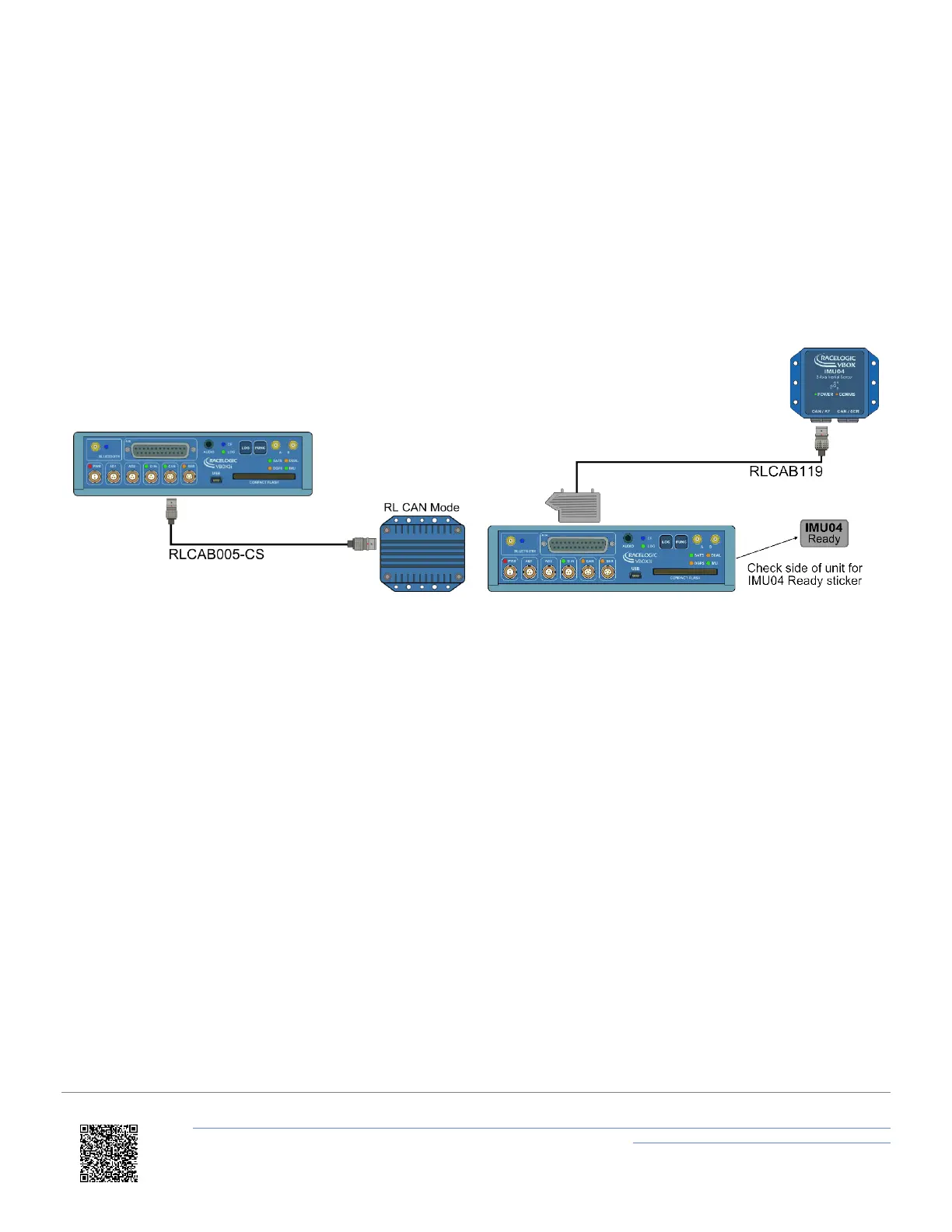
4. IMU04 – Connect CAN/KF port to VBOX 3i V3-V5 25W D analogue input port using RLCAB119 cable.
IMU03 – Connect either port on IMU to VBOX RL CAN port using RLCAB005-CS cable.
5. After IMU is connected, apply power to VB3i.
6. Enable IMU integration using either VBOX Manager or VBOX Setup.
VBOX 3i and IMU03 VBOX 3i V3-V5 and IMU04
Configuration
VBOX Setup Software
1. Ensure IMU04 is connected via RLCAB119, and the VBOX 3i is powered on.
2. Connect VBOX 3i to PC using RLCAB001 or RLCAB066-2 cable (RS232 or USB).
3. Open VBOX Setup and connect to VBOX 3i by selecting COM Port.
4. Select the 'GPS' menu and the 'Settings' tab, ensure that 'GPS Optimisation' is set to 'High dynamics'.
5. Select the 'Logging' menu and ensure that 'Log rate' is set to '100 Hz'.
6. Select the 'IMU' menu and tick 'Enable IMU integration'.
https://en.racelogic.support//Product_Info/VBOX_Data_Loggers/VBOX_3i_Range/VBOX_3i_User_Guide_(All_Variants)/12-1_-
_VB3i_IMU_Integration_-_In-Vehicle_Mounted
54