VB3i Analogue Input PIN OUTS
For PIN out information on other VB3i ports, click here.
V4/V5
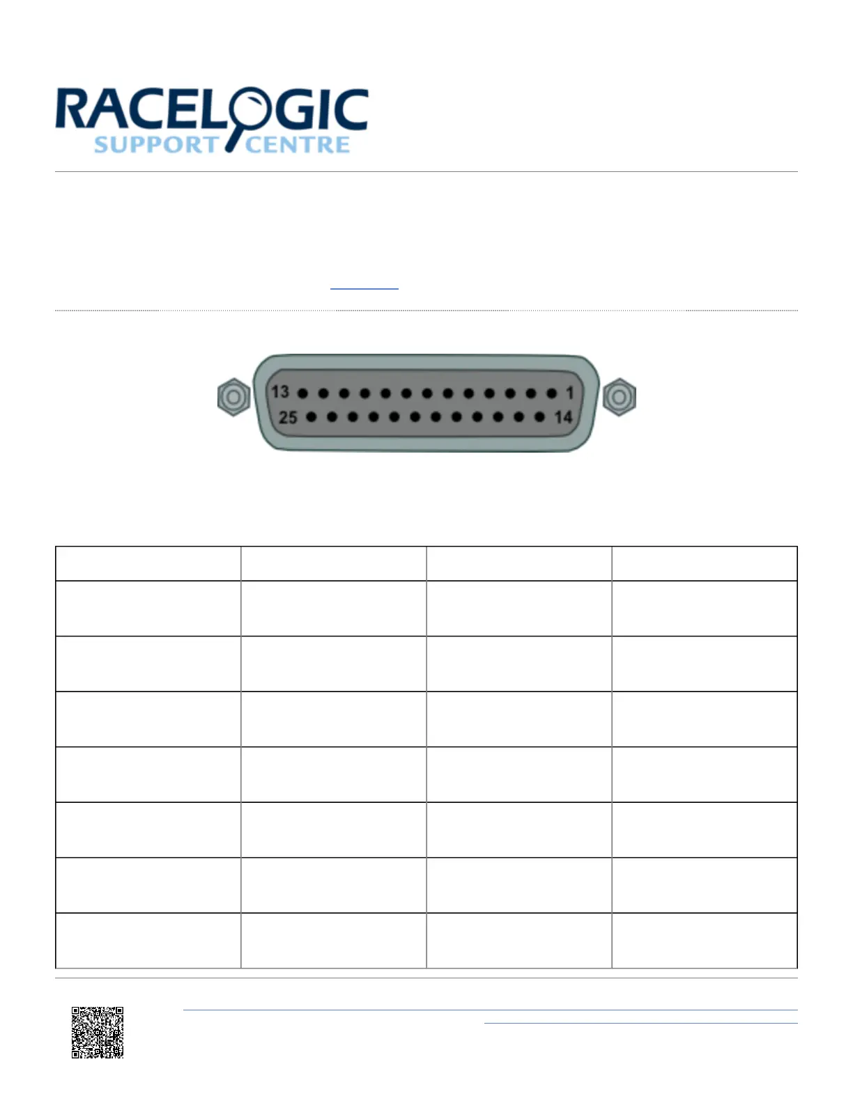
View of Sub-D 25-way socket
Note: A screw terminal connector block is available to purchase on request from your VBOX supplier.
PIN In / Out Description Range
1 I Isolated Channel 1 +
1.8 M Ohms input
impedance
2 I Isolated Channel 1 -
1.8 M Ohms input
impedance
3 I Isolated Channel 2 +
1.8 M Ohms input
impedance
4 I Isolated Channel 2 -
1.8 M Ohms input
impedance
5 I Isolated Channel 3 +
1.8 M Ohms input
impedance
6 I Isolated Channel 3 -
1.8 M Ohms input
impedance
7 I Isolated Channel 4 +
1.8 M Ohms input
impedance
https://en.racelogic.support//Product_Info/VBOX_Data_Loggers/VBOX_3i_Range/VBOX_3i_User_Guide_(All_Variants)/15_-
_VB3i_Technical_Properties/VB3i_Analogue_Input_PIN_OUTS
93