GB
46
Note: Fix the cables at short intervals (approx. every 500 mm)
so that they do not vibrate.
Note: When installing into the dashboard, make sure that the
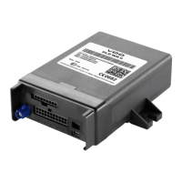
DLD
®
Wide Range II can be removed quickly, e.g. to carry out a
manual fi rmware upgrade or for the subsequent installation
of an antenna.
Tip:
Put the sticker (included in the package) over the DIP
switch and USB interface openings in the housing to prevent
any foreign matter getting into the device.
Installing the DLD
®
Wide Range II
Requirements
• Installation location determined
• DLD
®
Wide Range II confi gured
• Power supply and CAN interface cables installed