GB
47
Note: Please observe the notes from page 41 and
page 45 without fail.
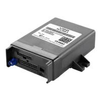
1. Fix the DLD
®
Wide Range II in the installation location. Screw
on the DLD
®
Wide Range II with two screws or fi x it with dou-
ble-sided adhesive tape. Regularly check for intact adhesion.
2. Connect the DLD
®
Wide Range II to the power supply and
CAN interface (see pages 47 and 48 and the fi gures on
pages 6 and 7).
• Optional: Connect the DLD
®
Wide Range II to the K-Line
interface (see page 49).
Connecting the DLD
®
Wide Range II to the
vehicle's electrical system
Caution: “Terminal 30” (permanent power supply) must be
tapped after the vehicle's master switch.
Caution: The
DLD
®
Wide Range II supply line voltage must
match the ignition voltage.