GB
48
3. Connect “Terminal 15” (ignition voltage) to connector pin 4.
4. Connect “Terminal 31” (ground) to connector pin 1.
5. Connect “Terminal 30” to connector pin 2.
See the wiring diagram on page 6.
Connecting the DLD
®
Wide Range II to the CAN
interface
Connect the DLD
®
Wide Range II to the CAN interface on the
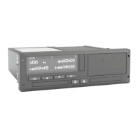
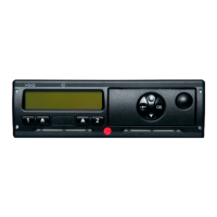
DTCO
®
1381 (see page 7).
The fi gure on page 7 shows the connector assignment for
the data communication of the DLD
®
Wide Range II with the
DTCO
®
1381 via the CAN interface and the corresponding
wiring diagram.
Setting the termination resistance
Delivery condition: CAN termination resistors set to ON.
The DIP switches for setting the CAN termination resistance
on the DLD
®
Wide Range II are located above the mini USB
connection (see page 8).
 Loading...