2
3. PRODUCT FEATURES
(1) The temperature sensor short-circuited or damaged, the controller be charging or
discharging at the default temperature 25° C.
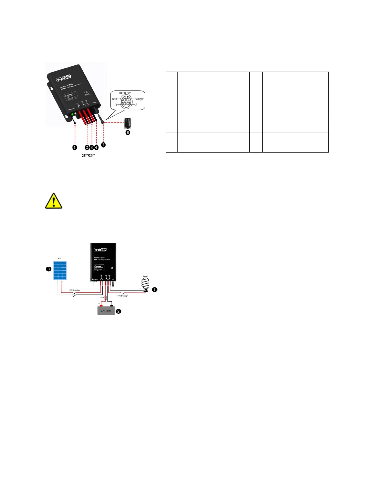
(2) The port can provide the DC power supply of 5VDC/150mA and have the short circuit
function.
Note: When the RS485 communication port is not working, the waterproof cap must
be installed to prevent water getting in.
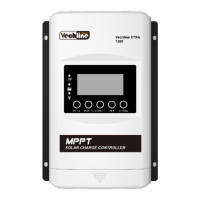
4. WIRING
Connection order
1) Connect components to the charge controller in the sequence as shown above and pay
much attention to the “+” and “-”.Please don’t insert the fuse or turn on the breaker during the
installation. When disconnecting the system, the order will be reserved.
2) After power on the controller, check the battery LED indicator on the controller, it will be
green. If it’s not green, please refer to chapter 10.
3) Connect a fuse in series through battery positive (+) in the circuit and the battery circuit
fuse must be 1.25 to 2 times to the rated current. The installed distance is within 150mm.
Load self-test function
The load is ON when the controller power on 10s. After 10s it will restore to set working
mode.
Charging Status LED
indicator
PV Positive and
Negative Wires
Battery Status LED
indicator
Battery Positive and
Negative Wires
Load Positive and
Negative Wires