6
Wiring Instructions
Wire used for this installation must have a temperature rating of at least 90°C. be either 14 or
16 AWG, and be color coded. Splicing alarm power with TL
S Console power will cause
improper operation of the monitor.
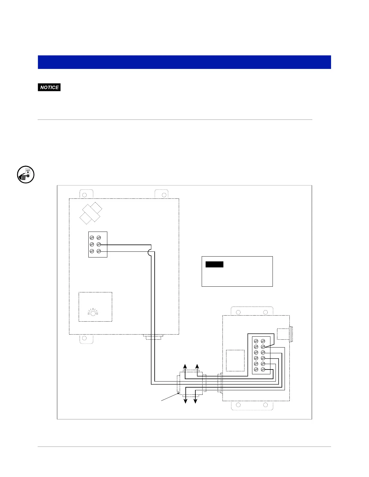
Wiring Overfill Alarm with Acknowledgment Switch
1. Pull two wires from the switch to the Overfill Alarm.
2. Pull two wires for line and neutral from the switch to the power panel.
3. Pull one wire from the switch to the TLS Console for connection to the alarm relay.
4. Pull one wire for line from the alarm relay in the TLS Console to the power panel.
5. Turn power Off and connect wiring according to the wiring diagram in Figure 3 and Table 1.
Figure 3. Overfill Alarm/Acknowledgment Switch wiring connections
1234 56
To power panel
L N
1
2
3
To Console Relay -
See Console Connection
Table in this manual
Ack Switch
(cover open)
Overfill Alarm
(cover open)
Customer supplied
junction box
Horn Time
Delay Relay
NOTICE
MAKE GROUND CONNECTION IN
ACCORDANCE WITH LOCAL CODES.
 Loading...